Getting Started
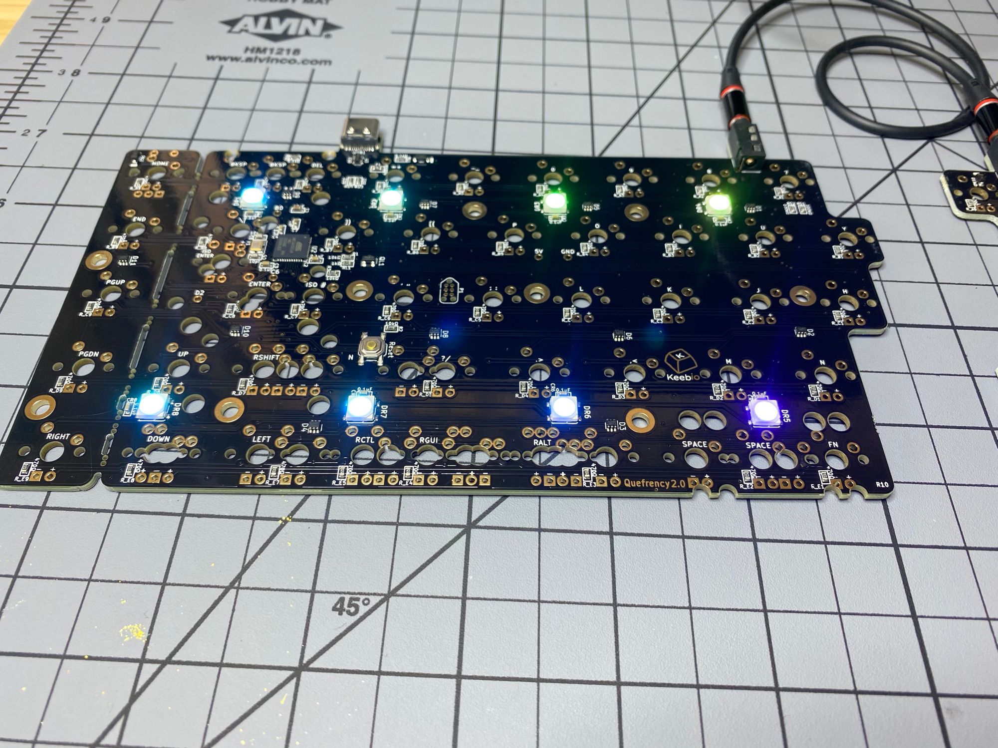
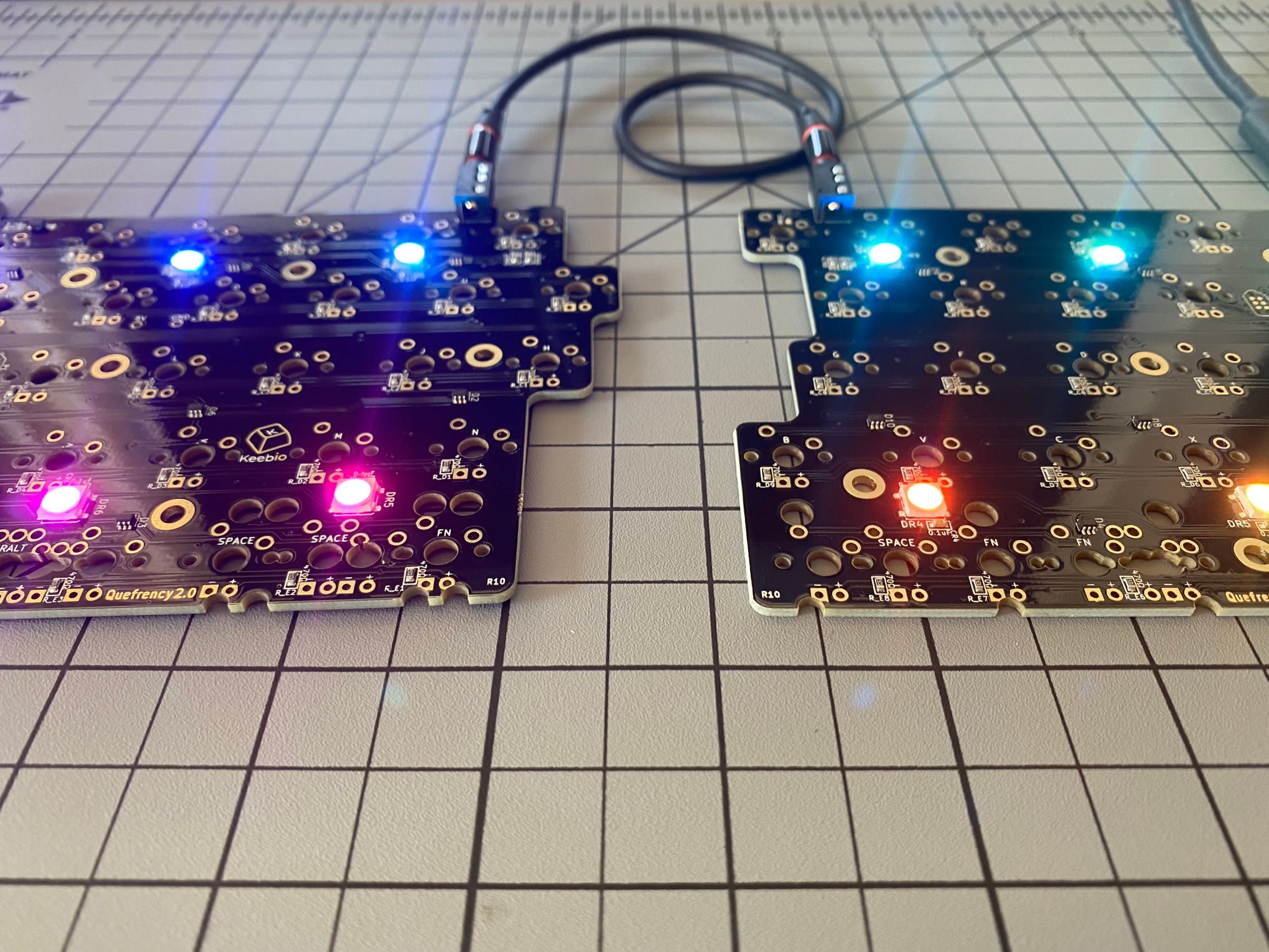
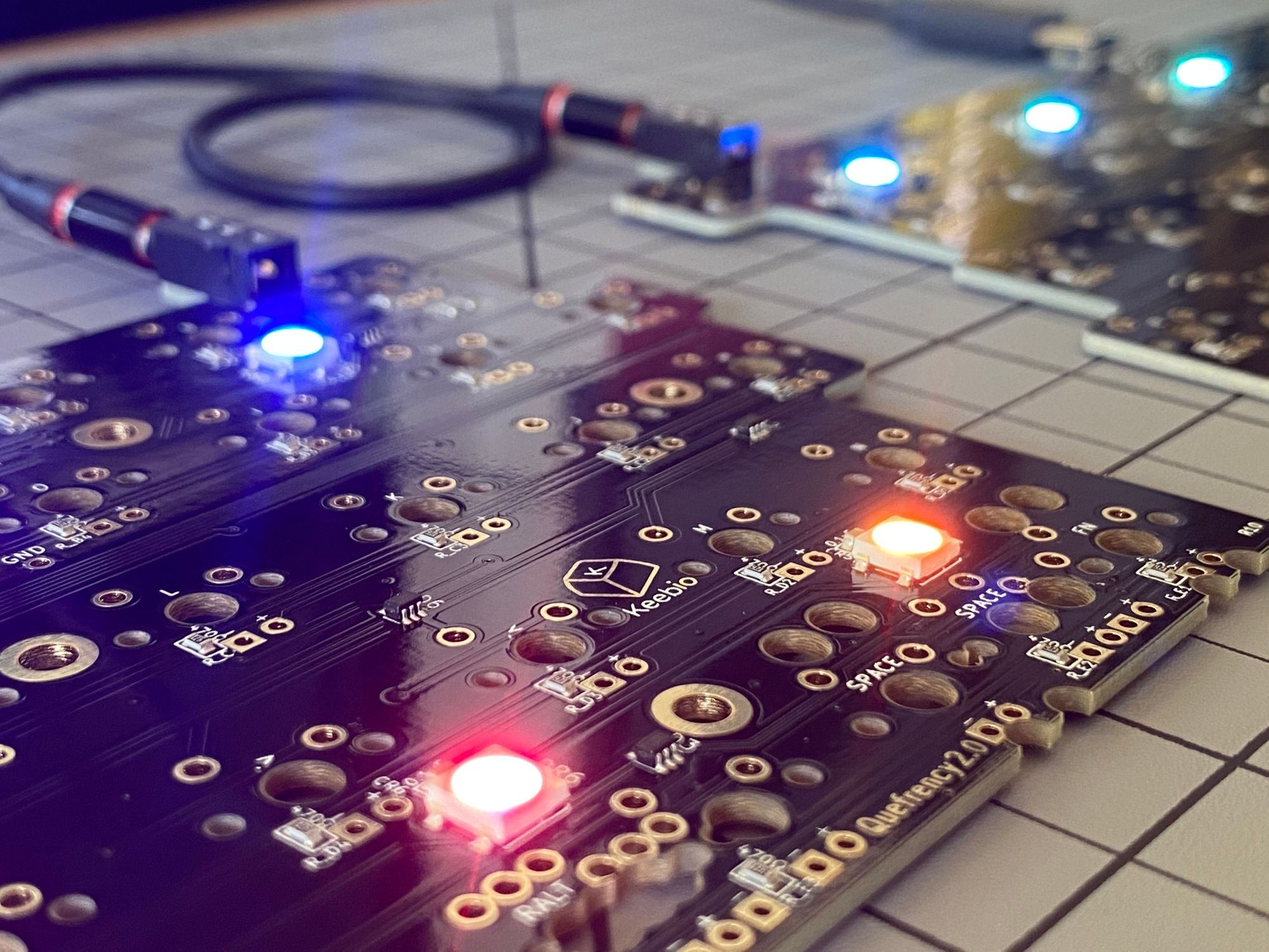
The first thing I did after receiving the board was plug it in, connect the TRRS cable, and flash the VIA version of QMK onto the board. It works, the LEDs work, and after testing each switch socket with tweezers, they work. Time for the fun stuff.
Staging everything
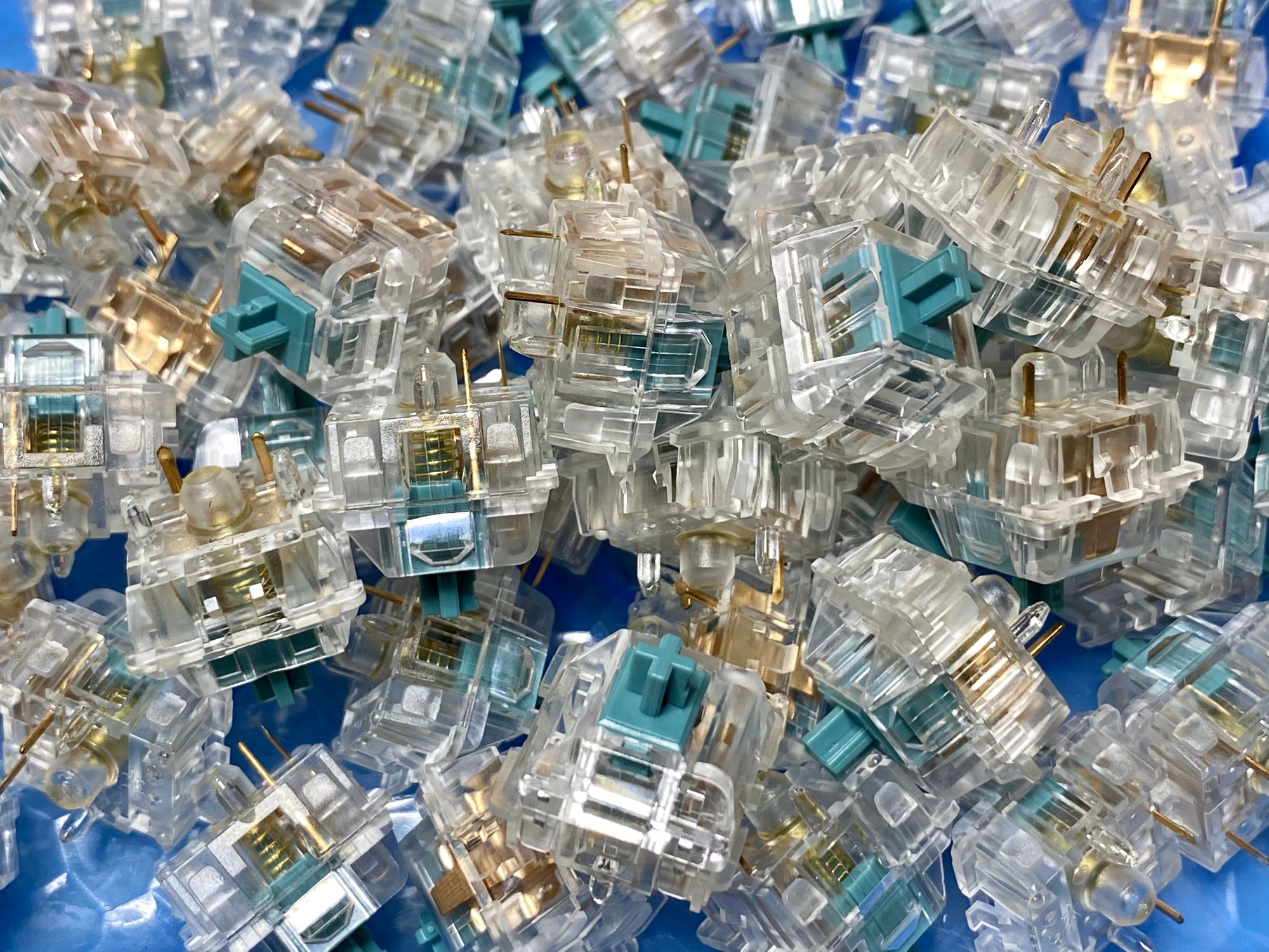
I gathered all the materials I would need to complete the board. Stabs, switches, rotary encoders, PCB's, soldering tools, etc.
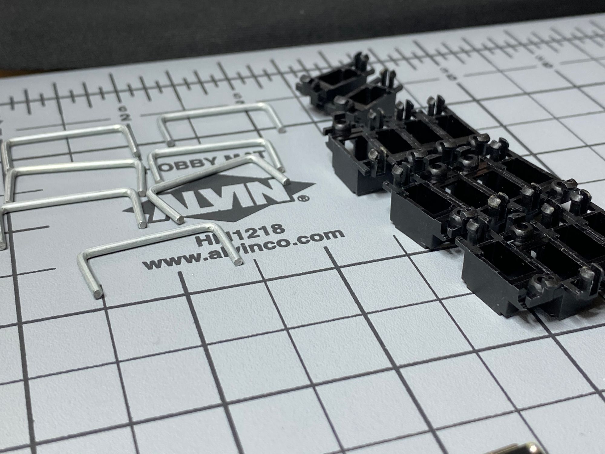
I then popped the stabs into the board and put in the rotary encoders. I tacked a single pin on the rotary encoders, made sure it was nice and straight, then soldered the rest of the pins.
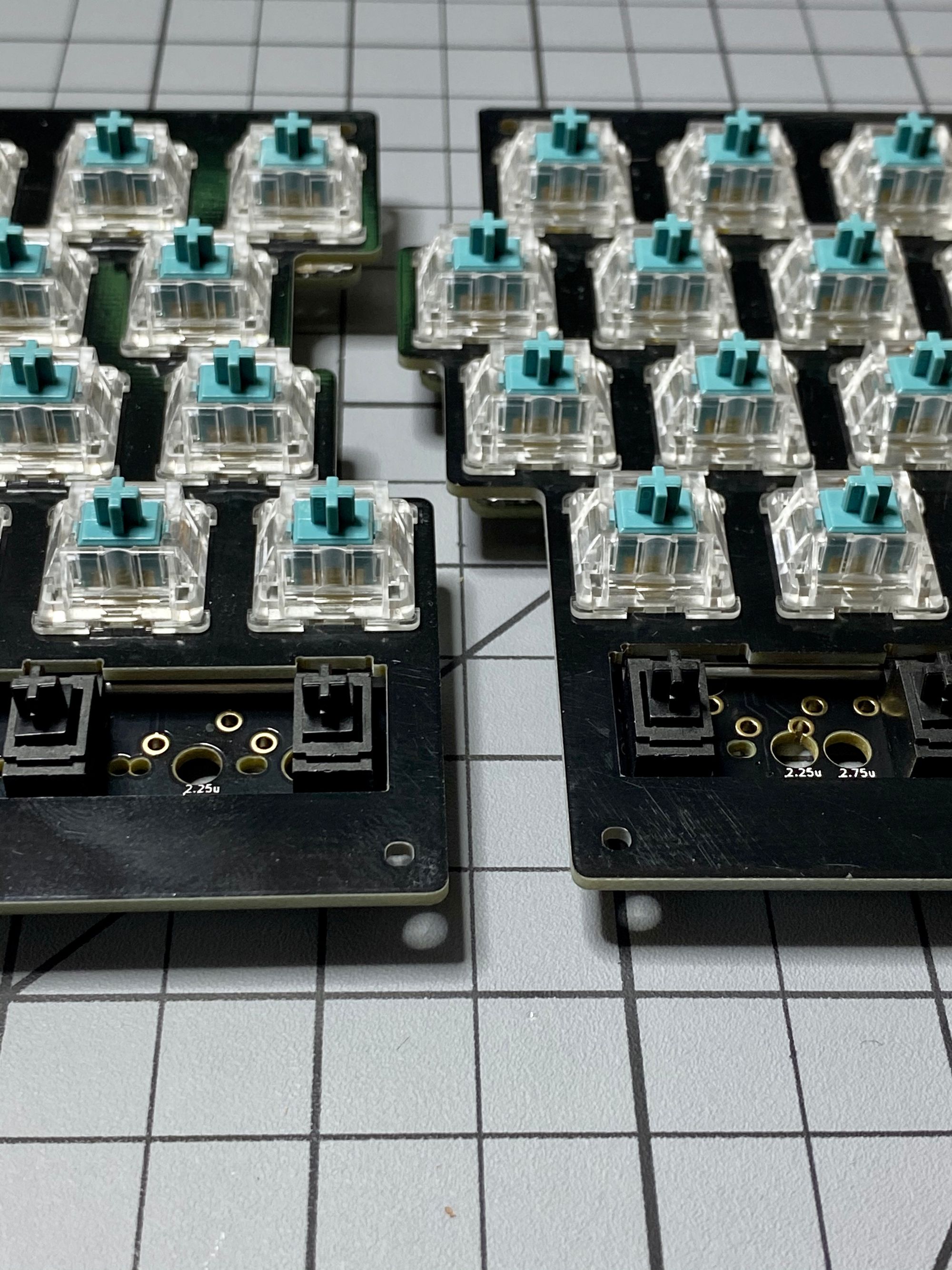
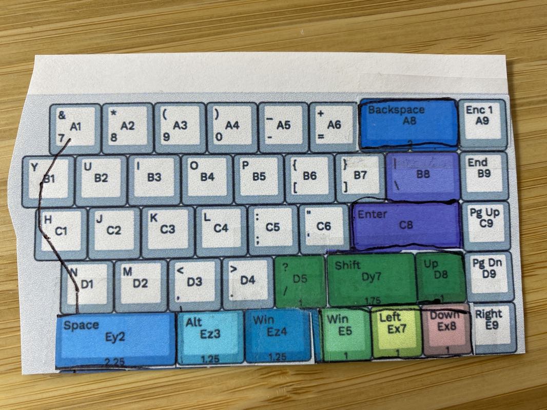
The board supports many different layout configurations, as show in the image below.
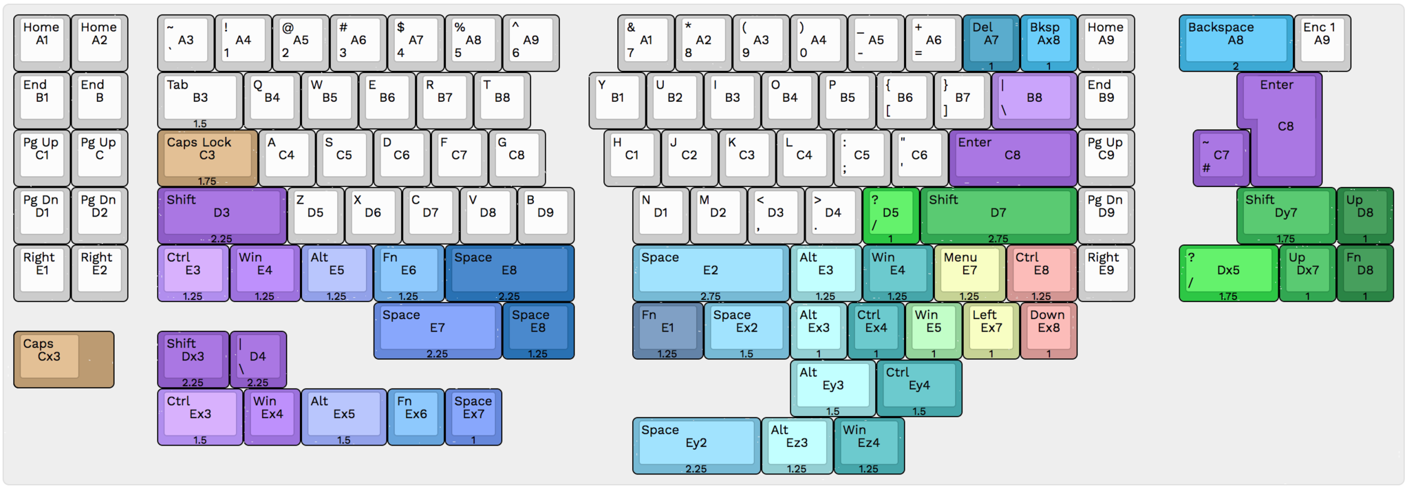
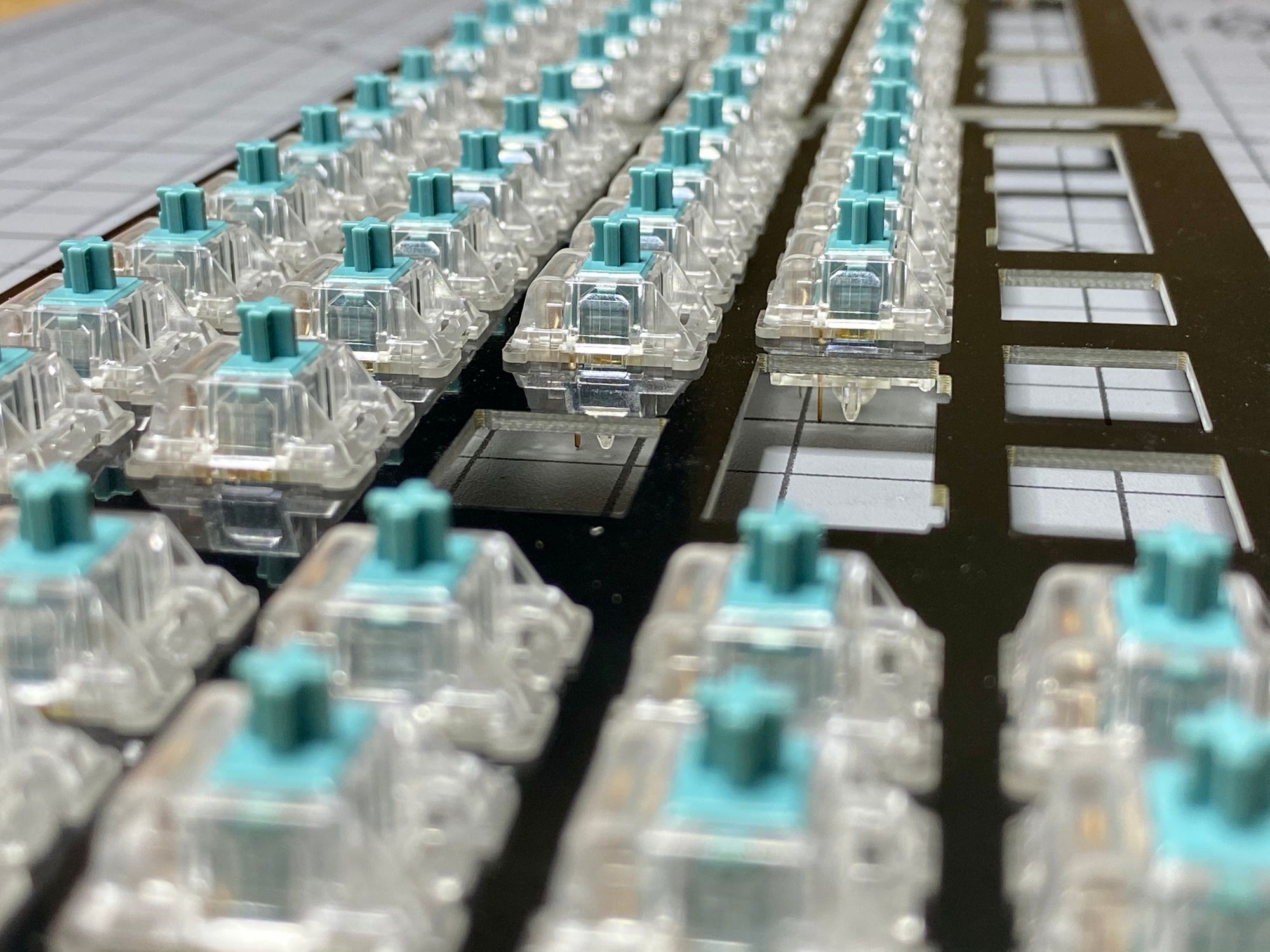
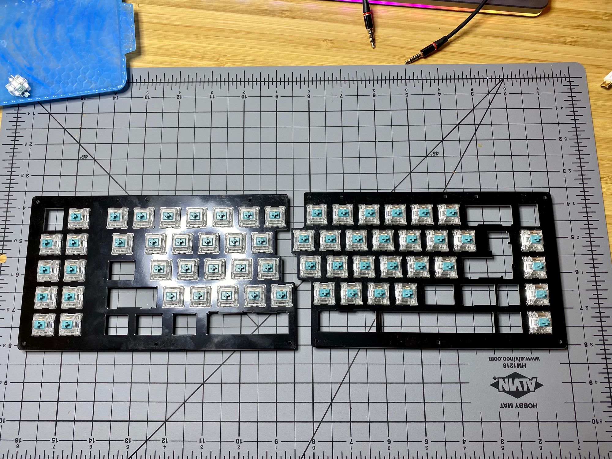
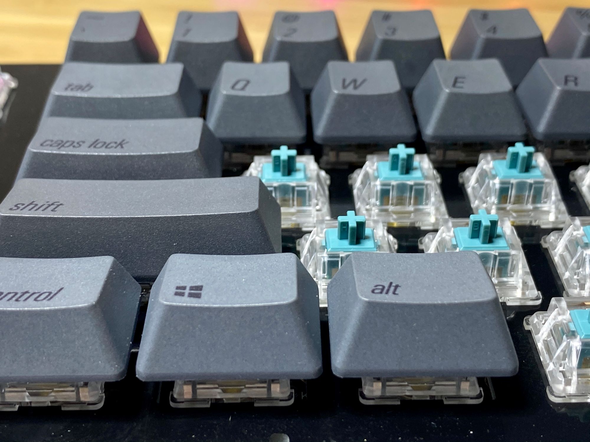
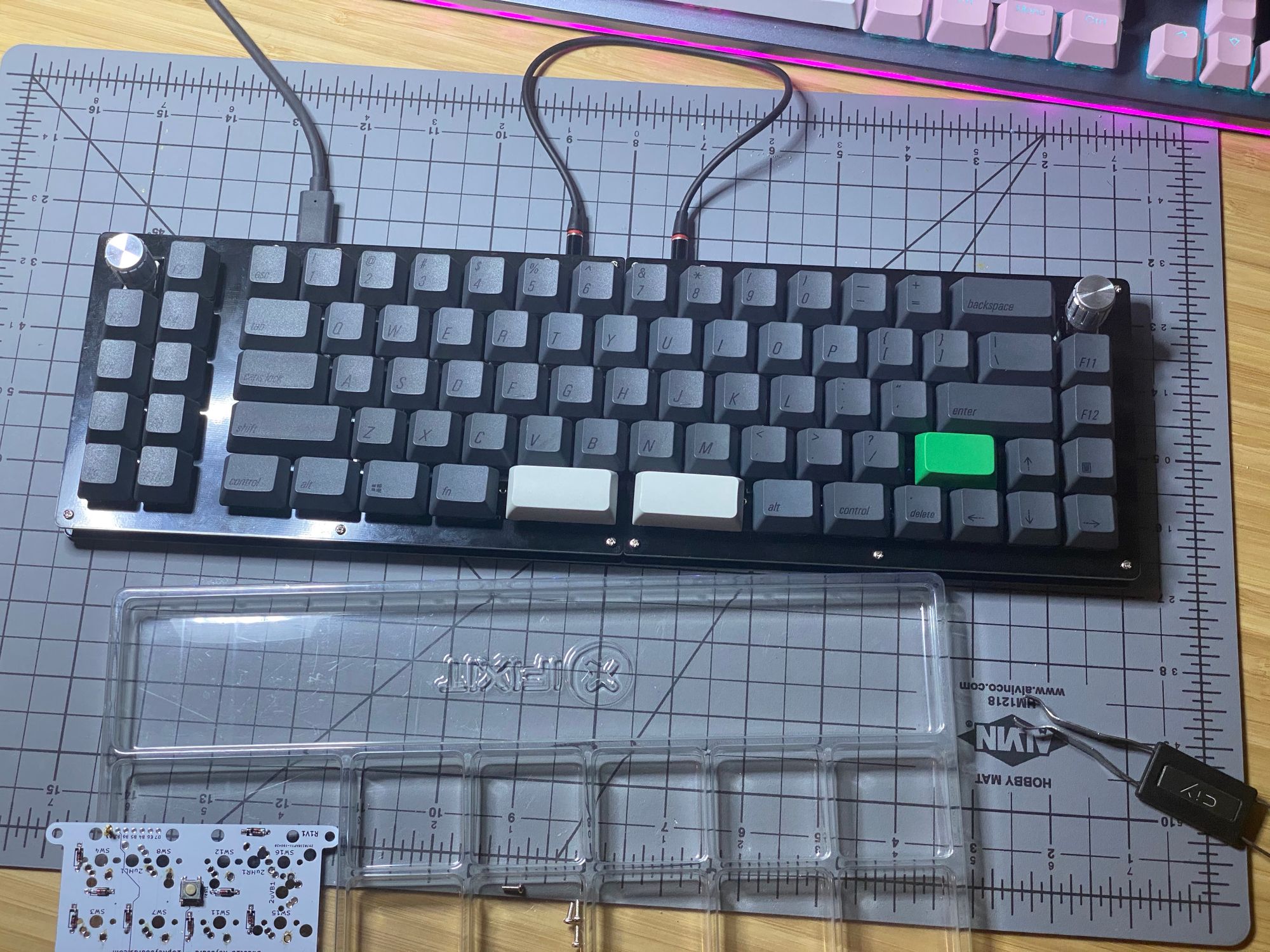
Instead of YOLOing the build, I decided the do a test fit before I soldered any switches. I knew I wanted both the macro pads and the rotary encoders, so that removed a couple of layout options. I really recommend picking and testing your layout prior to soldering.
Time to melt things
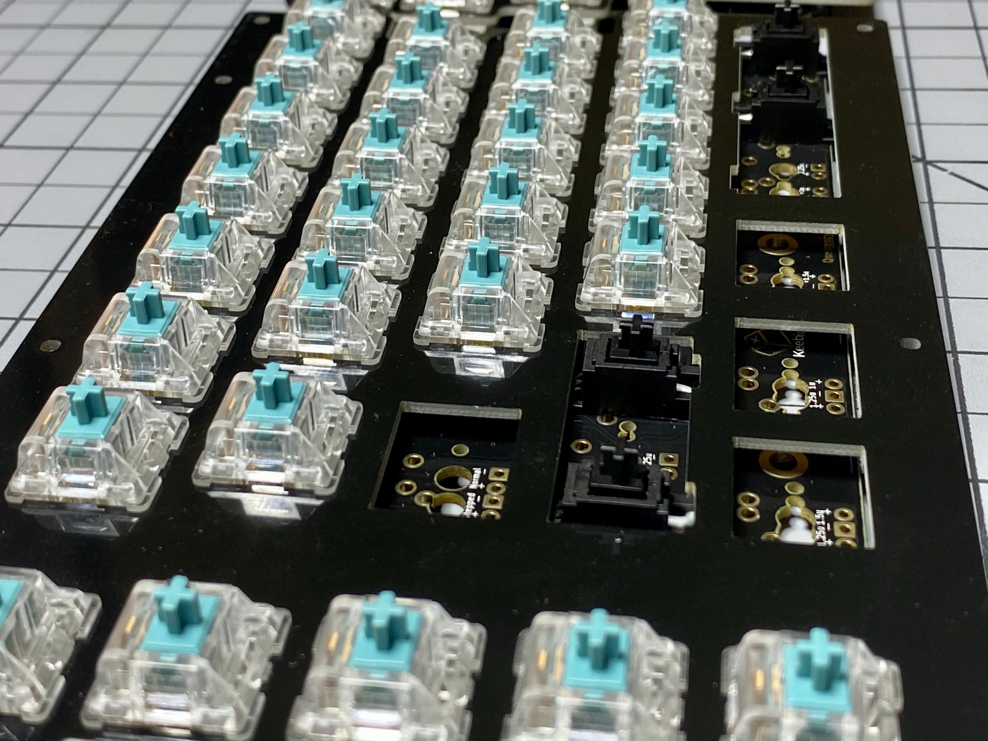
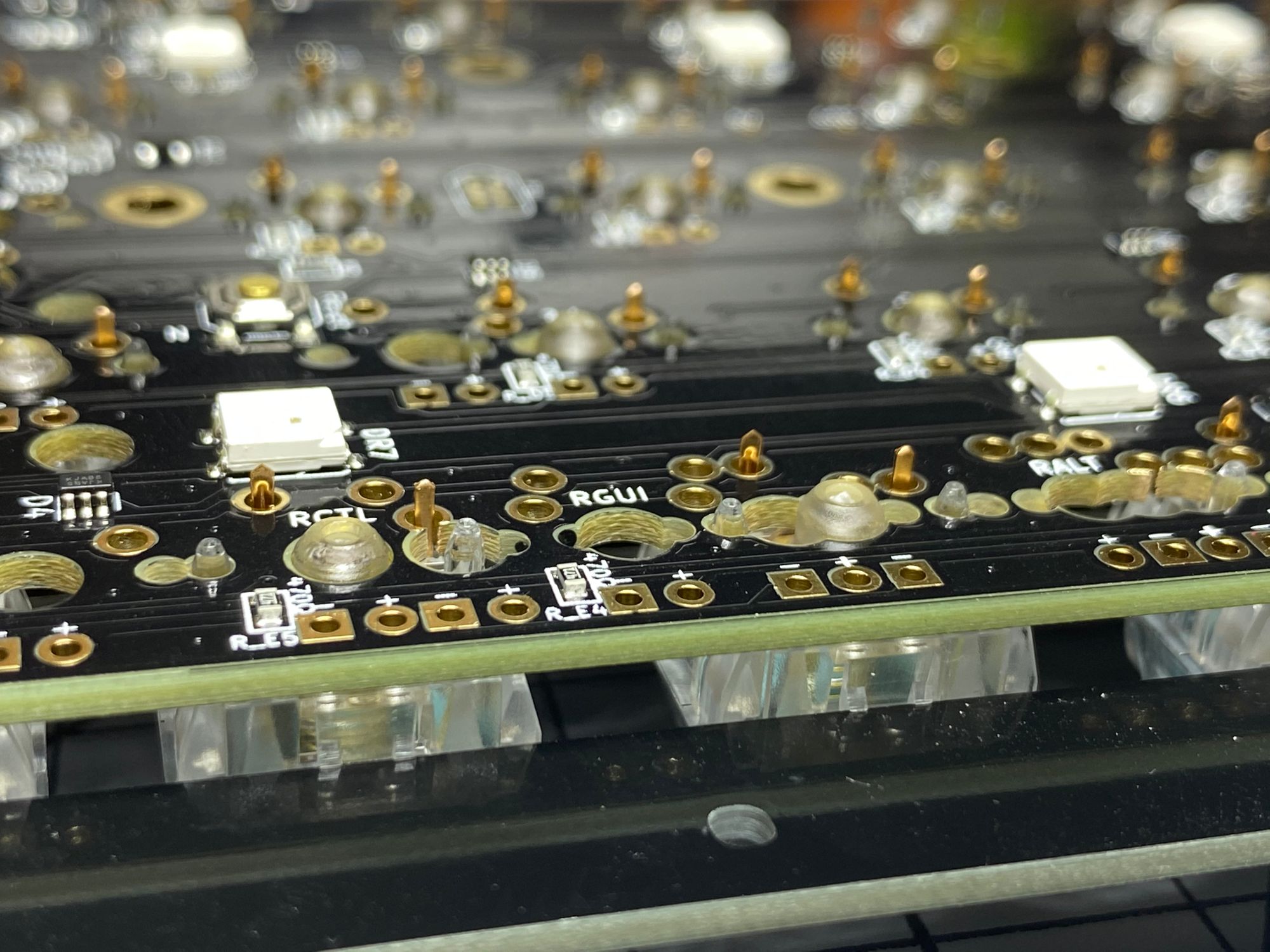
Now that I've picked a layout, its time to melt everything together. Due to the wide variety of layouts available, some of the plated holes in the board don't form a complete circle. This doesn't cause any problems but wasn't something I had seen before.
Wrapping up
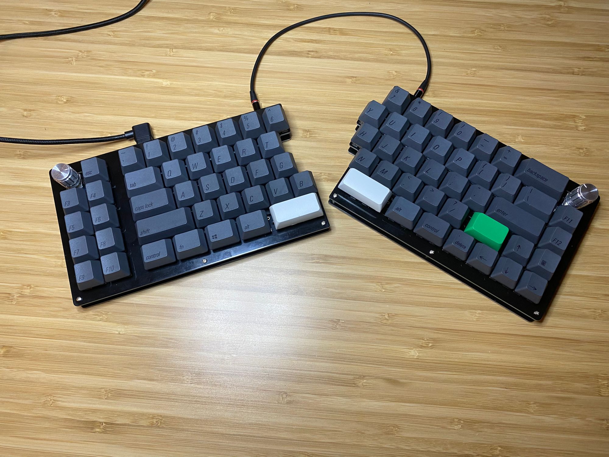
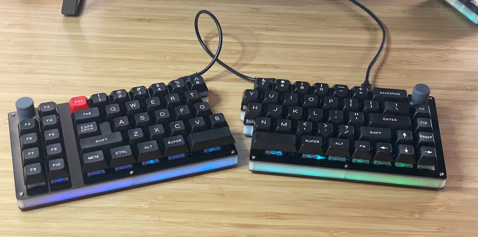
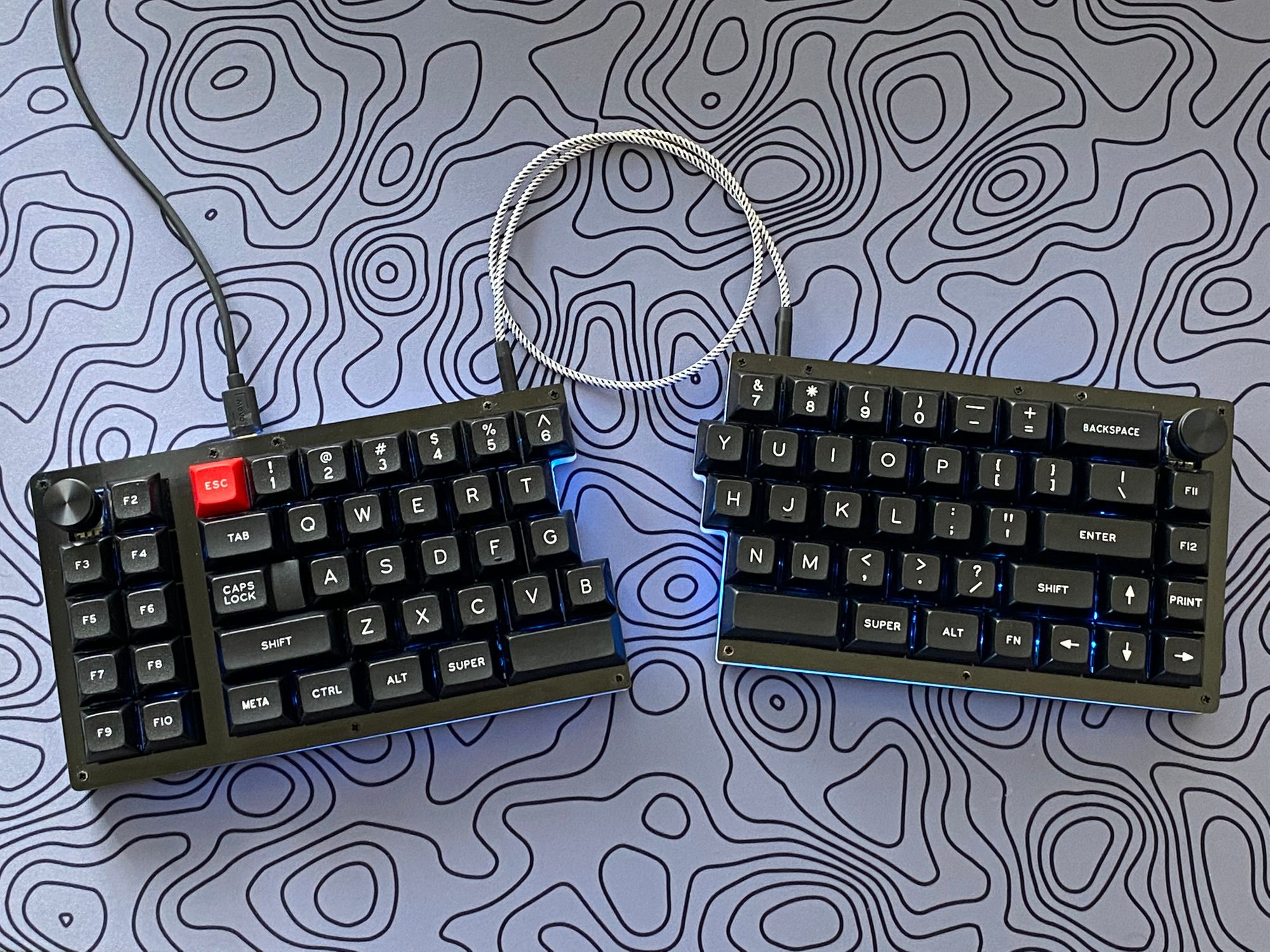
After everything had been soldered, I connected the board back to my computer and tested all the keys. Everything worked great! I used the included stand offs to create the case/frame and used rubber feet on the bottom of the board to stop it from sliding.
FIN
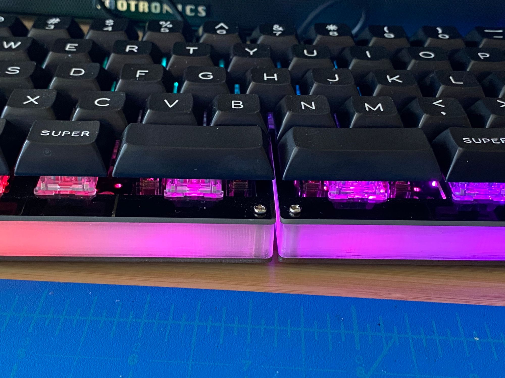
I'm really happy with the finished product. It's a solid keyboard and it's helping me get my touch typing back to Mavis Beacon levels. I didn't think I'd want LED's under the keys but after typing in the dark a bit, I changed my mind. I bought some 3mm flat top warm white LEDs. I haven't installed them yet - I think keeb.io will be releasing an acrylic case soon. If the case requires any desoldering, I'd rather only do it once (see updates below). If I have to desolder all the switches, I would replace the current stabs with screw in stabilizers that have been lubed and clipped. I also have been using gaff tape for the infamous band aid mod . I think it dampens the sound better and is less pingy. Also easier to add/adjust prior to placing the stab.
Firmware Notes
VIA is a great tool for someone like me. It has an easy to use GUI and on the fly macro creations. At of the time of writing, VIA does not support modifying the rotation motion (jogging left or right) on the encoders. It can only modify what happens when the encoder is pressed in. I read the QMK documentation and modifed the via keymap to have the top left encoder toggle screen brightness and the top right encoder toggle volume up/down. Depressing the left encoder puts the machine to sleep and drepressing the right encoder mutes the volume. If you're new to modifying firmwares, there's nothing to be scared of. It's just a text file. I would recommend looking through the firmware for the board and seeing how to default options are set. From there, you can use QMK's key codes to add/replace what you want.I thought these would be a novelty to use, but I've found that I've come to rely on them frequently and find myself missing the encoders on boards without them.
Updates: Actually using the board...
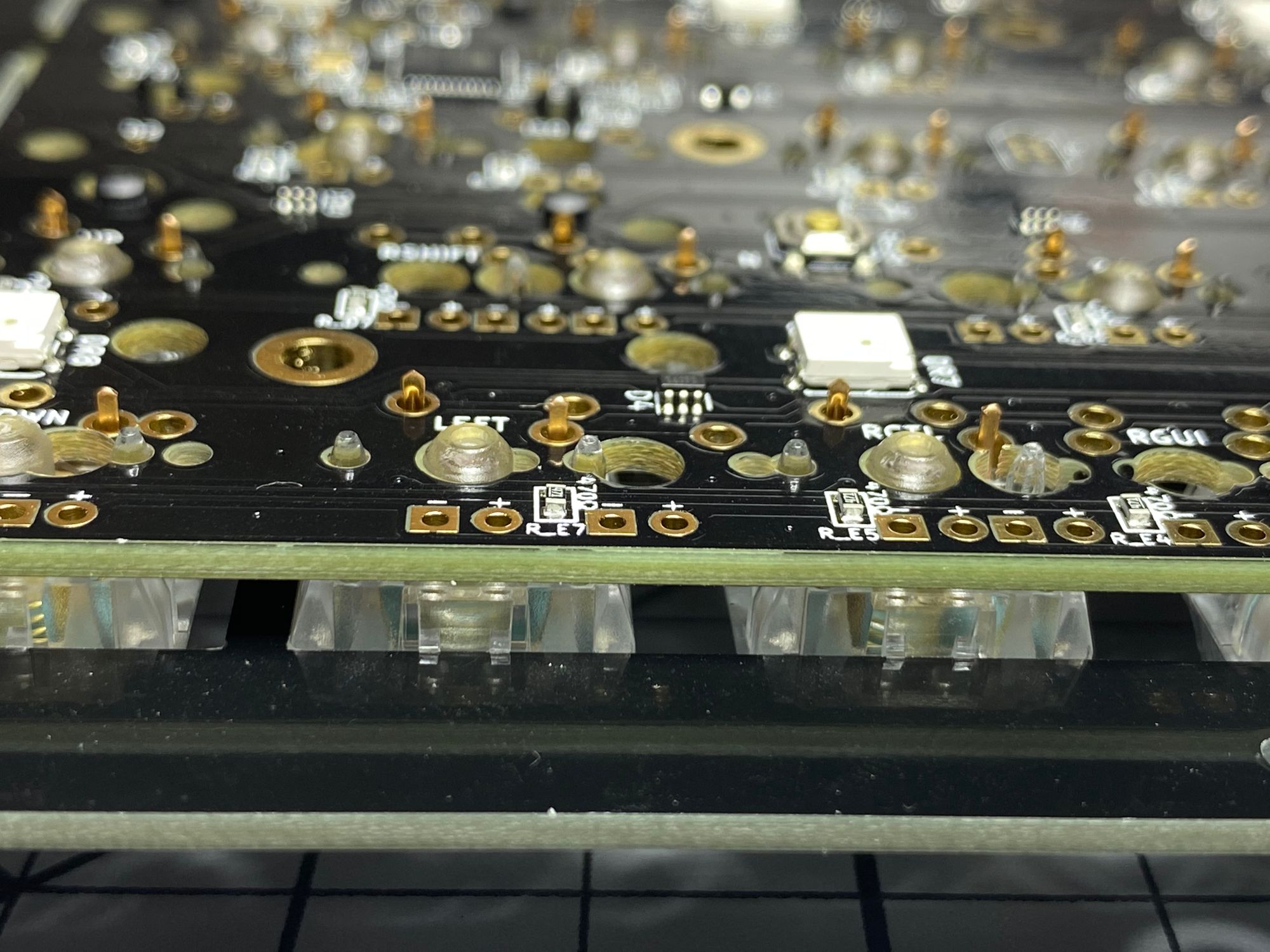
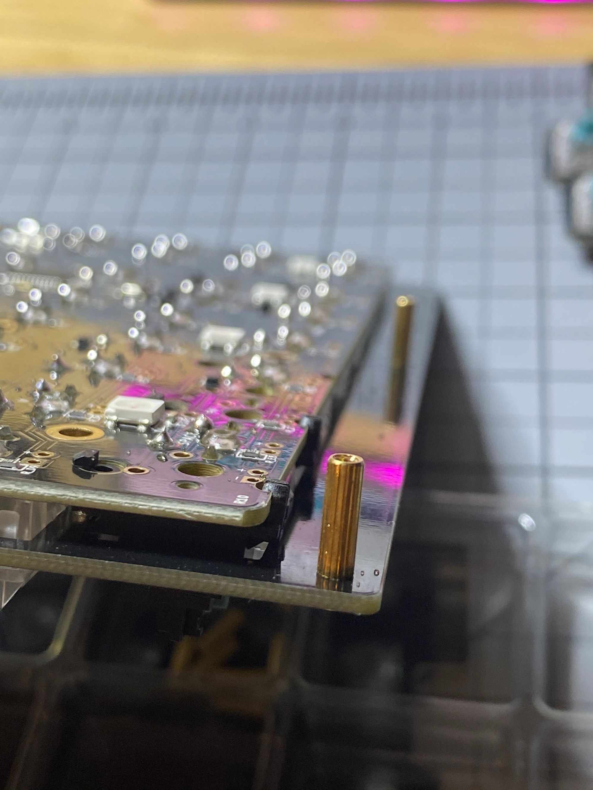
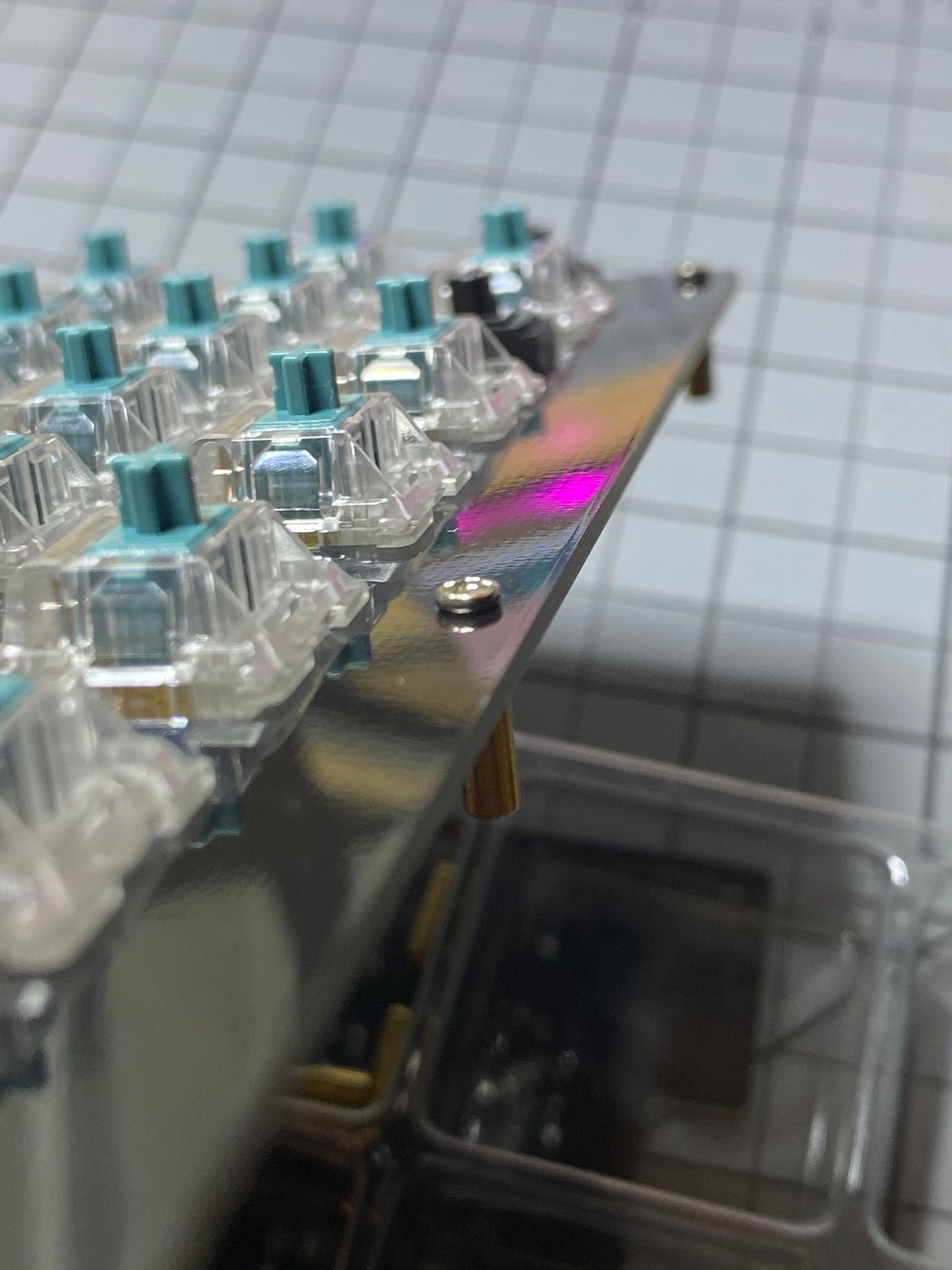
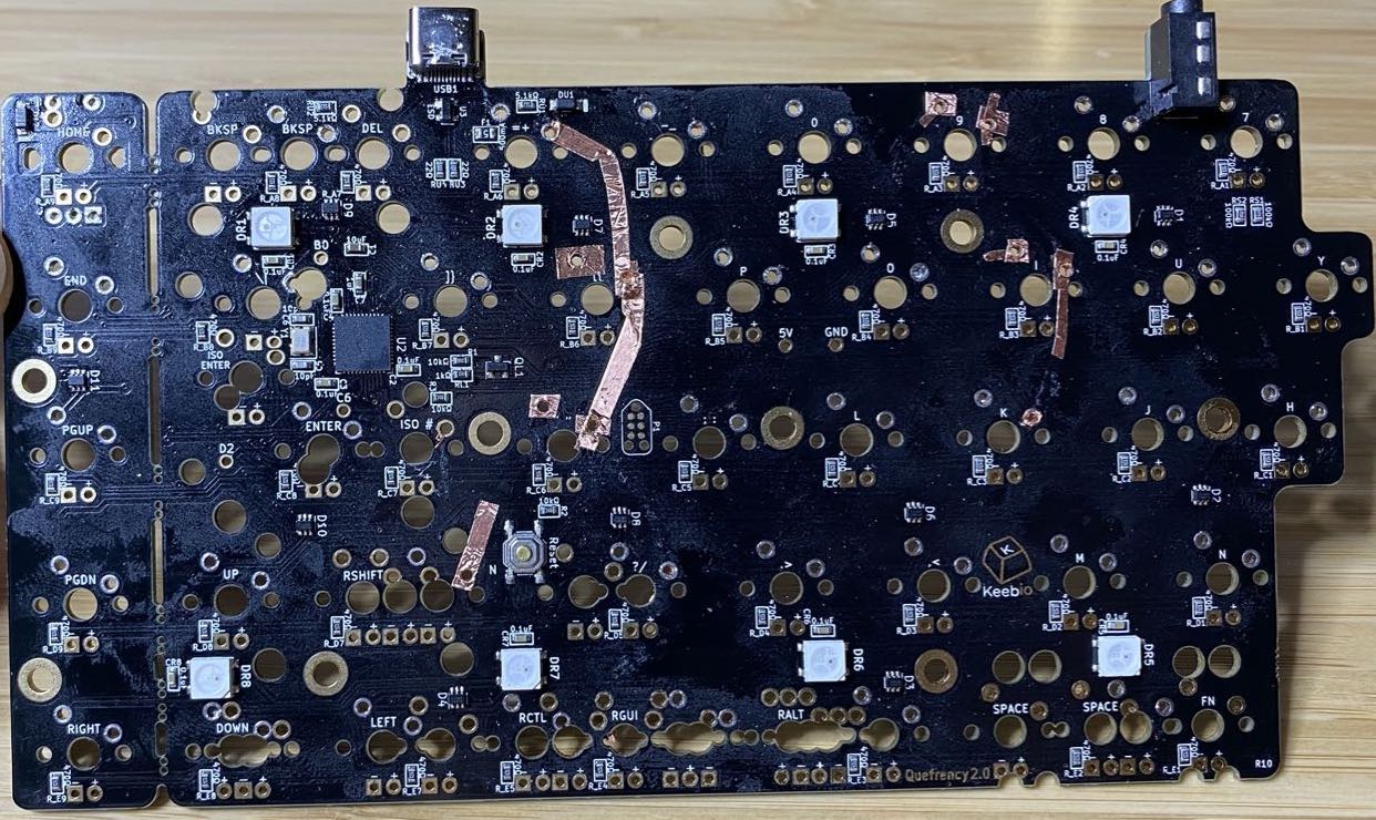
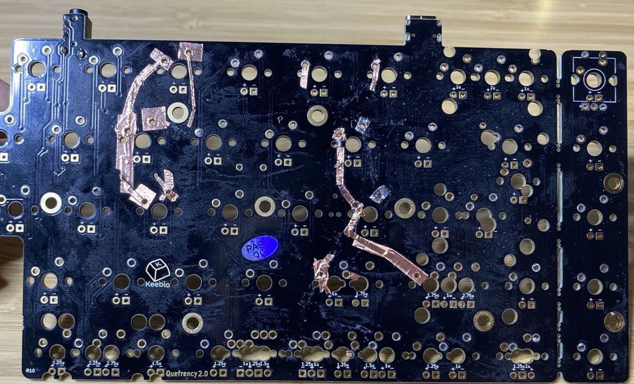
After using the board for a while I decided to swap in new stabs and add backlighting. While I managed to unsolder everything to add new stabs, I really f'd the boards up and wound by buying a new set of PCB's. Don't let $20 worth of parts ruin your keeb life. Buy good, screw in stabs and lube them before building your board. Here's some keyboard gore from the attempted fix:
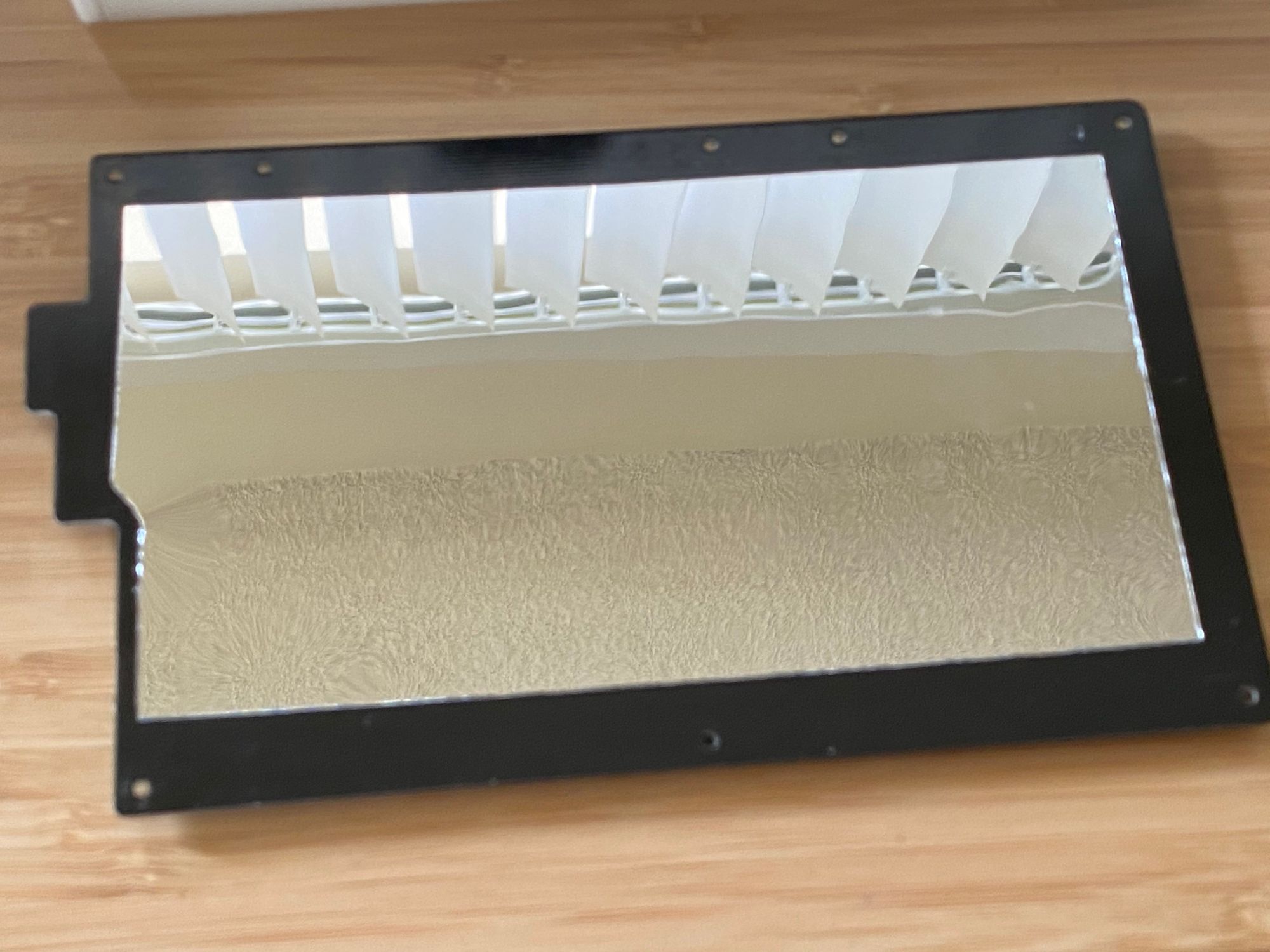
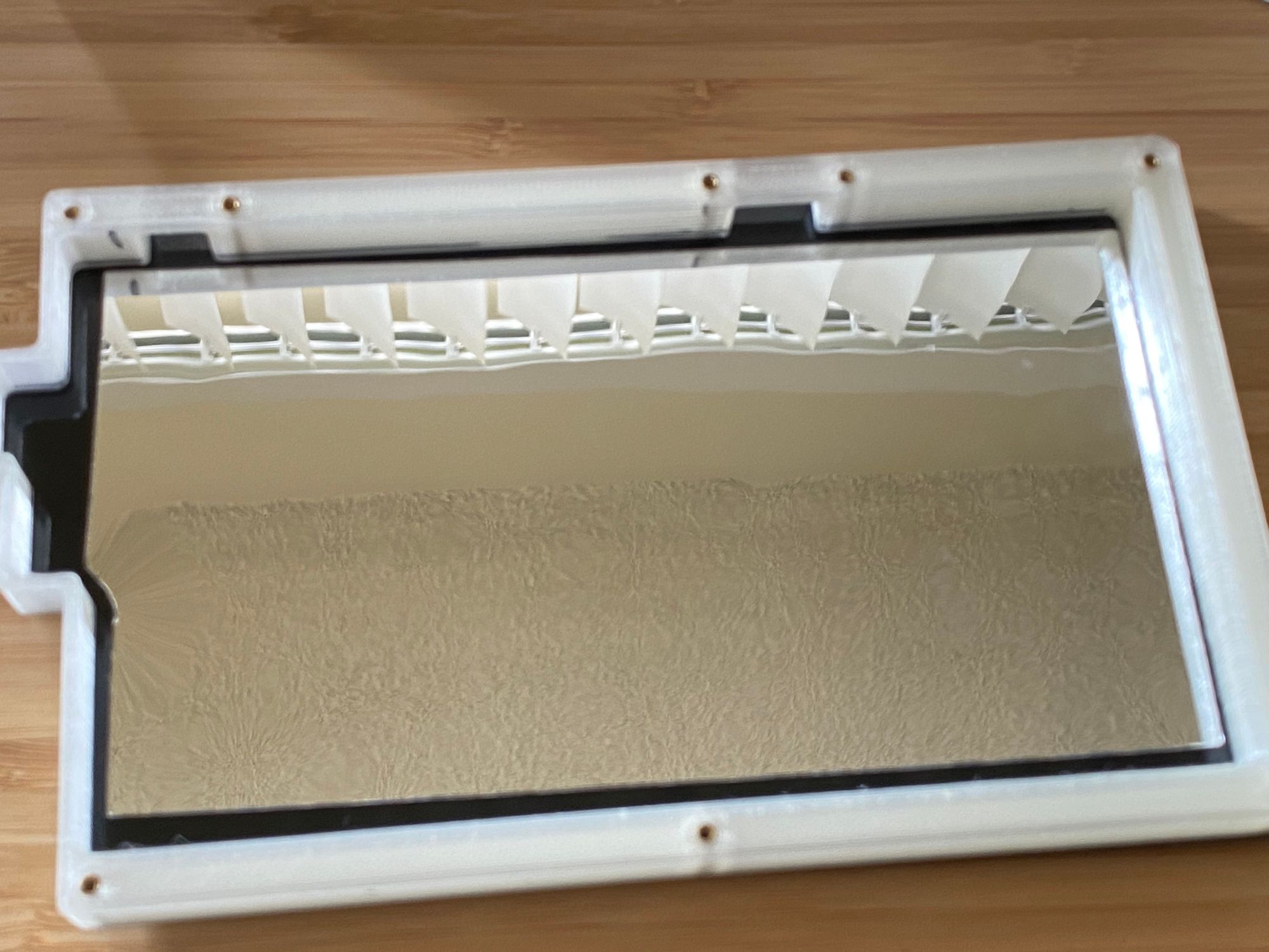
After getting the new PCB's, I soldered everything back together. I passed on the backlighting this time... it just didn't do too much for me. I had my cousin print some midlayers (from keebio's Github) so the board would have an evenly distributed glow. Thing is - once the midlayers were added, the glow wasn't as bright as it had been before. I was in too deep at this point to stop, so I bought some flexible mirrored material with a sticky back off Amazon. I then cut it to fit and stuck it in. The glow was way brighter - problem solved.
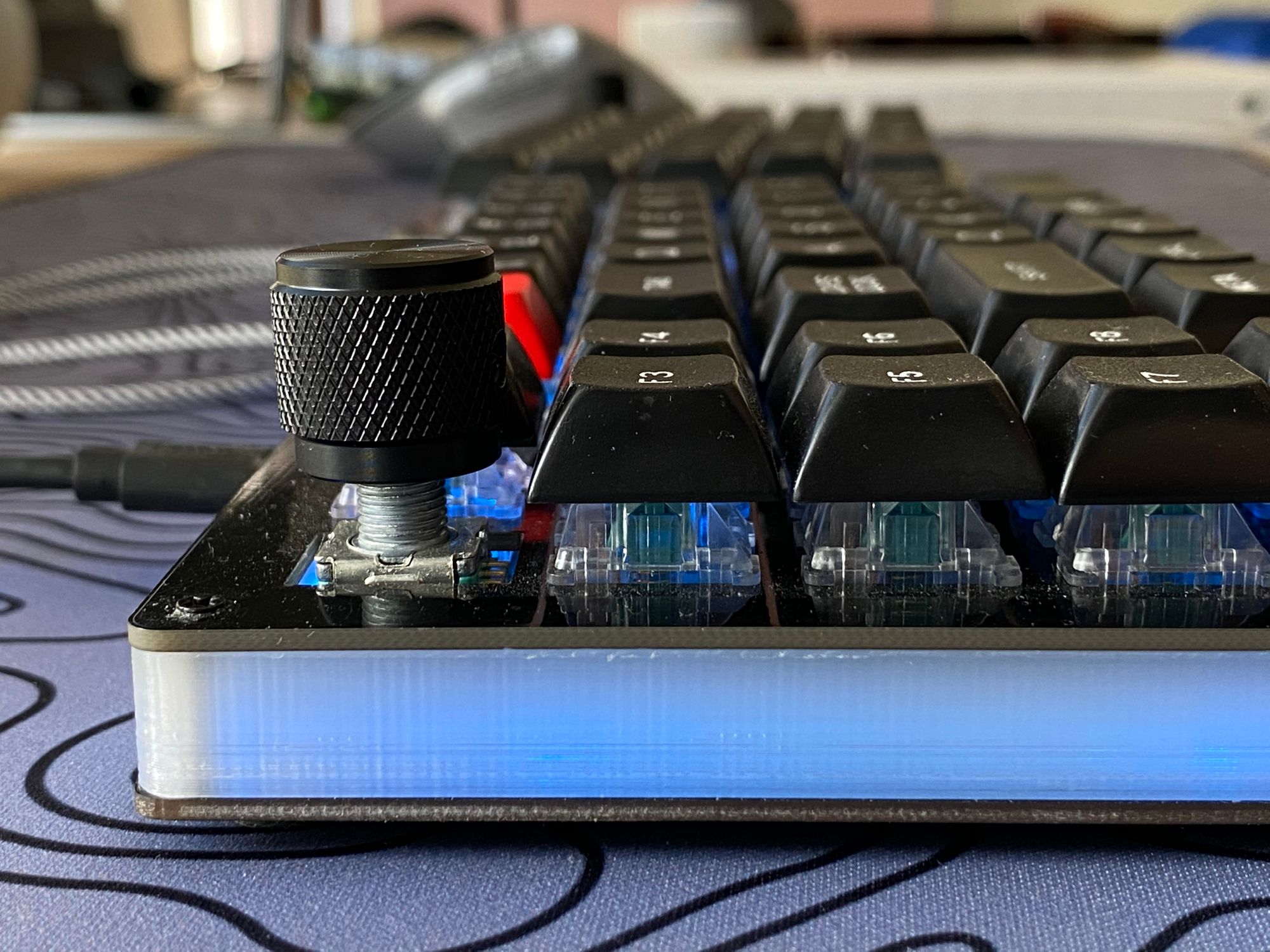
Since I was past the point of no return, as mentioned above - I wound up upgrading from my original cheapo Amazon keyset to a DSA profile set from PMK. PMK also sells single keys, so I was able to get spacebars in the perfect sizes. After seeing that the keyset didn't match with the encoder knobs, I bought nice, knurled encoder knobs to match. At this point, it would have been more cost effective and less frutration to just burn a pile money.
I had a lot of fun though and learned a tonne about hardware, software, and troubleshooting. The keyboard is a beautiful tool that I made myself and will last for a long time. Unless I decide to desolder it again.