Overview
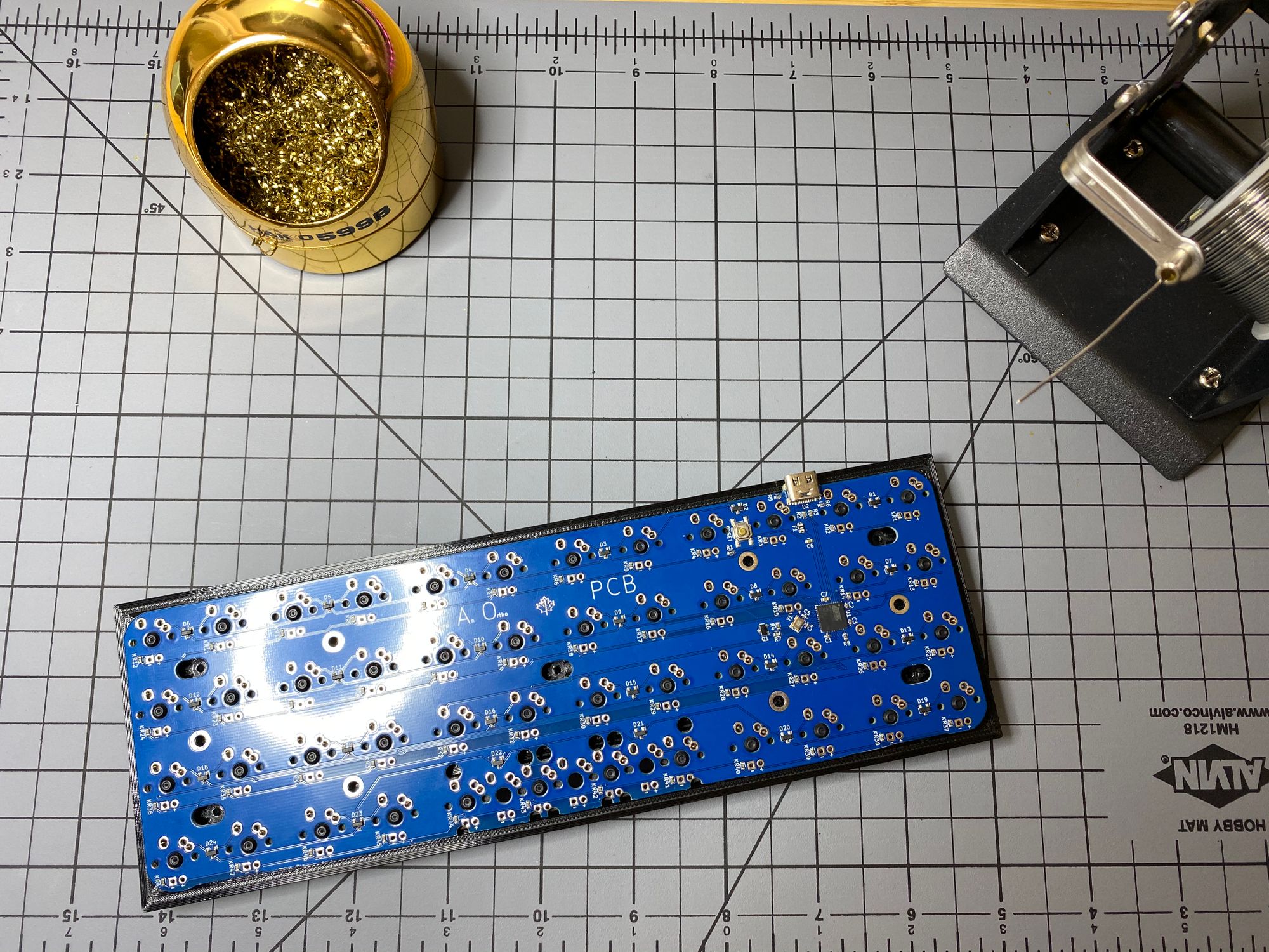
I decided to purchase the JNAO (Just Need An Ortho) board from keeb.io and do a custom keyboard build from the PCB up. It comes as a 5x12 layout with a break off bottom row to convert it to a 4x12 layout. I decided to use the 4x12 layout.
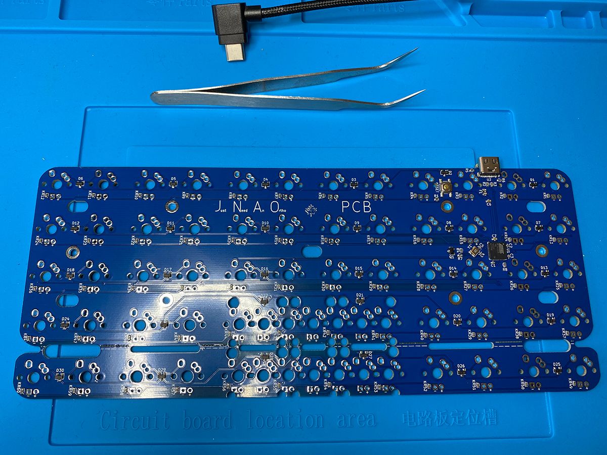
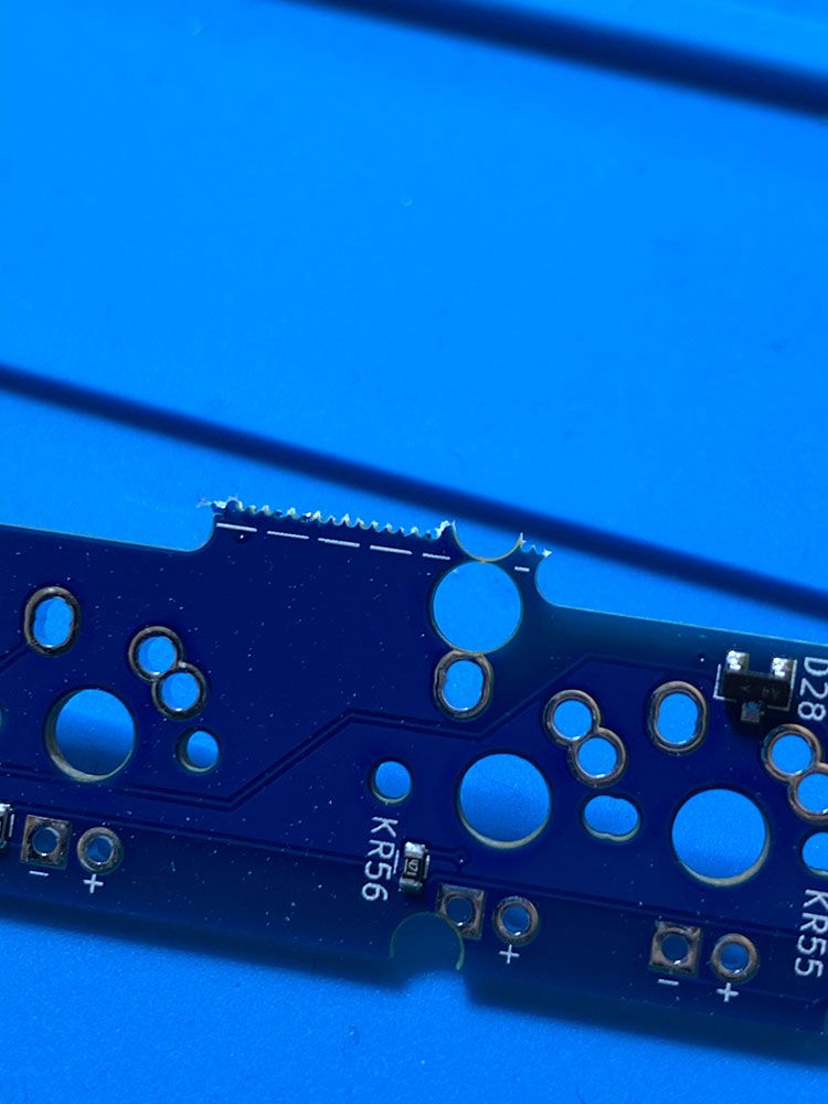
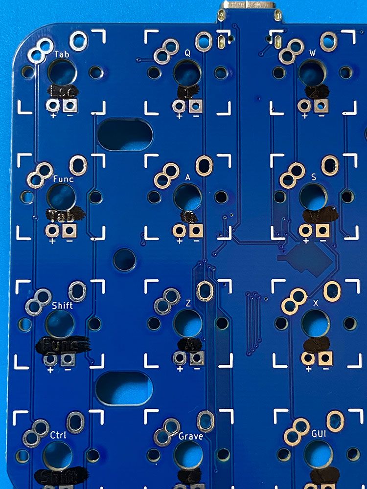
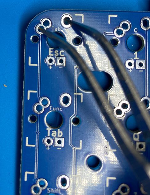
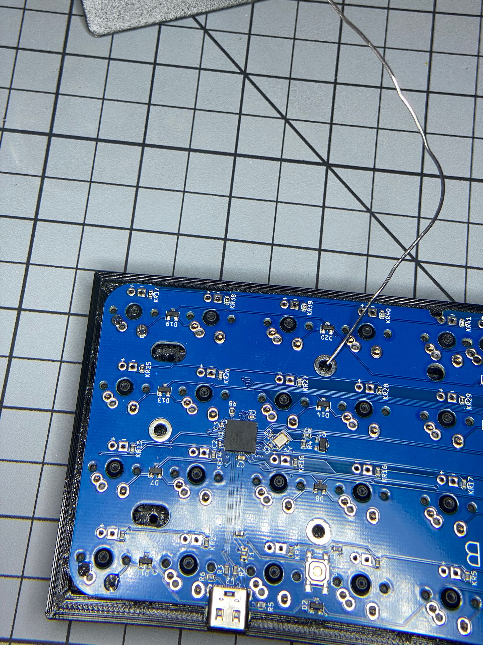
The bottom row broke off easily. I gently applied pressure down on that row while lifting the top of board towards me. I used a Dremel to sand off the rough edges left from the break.
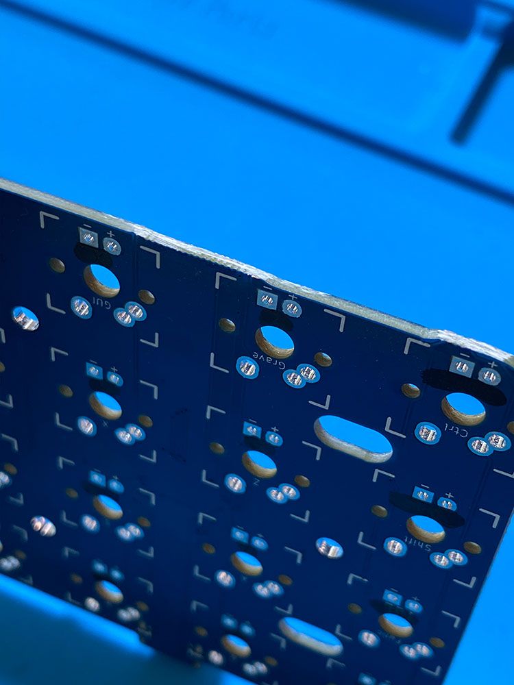
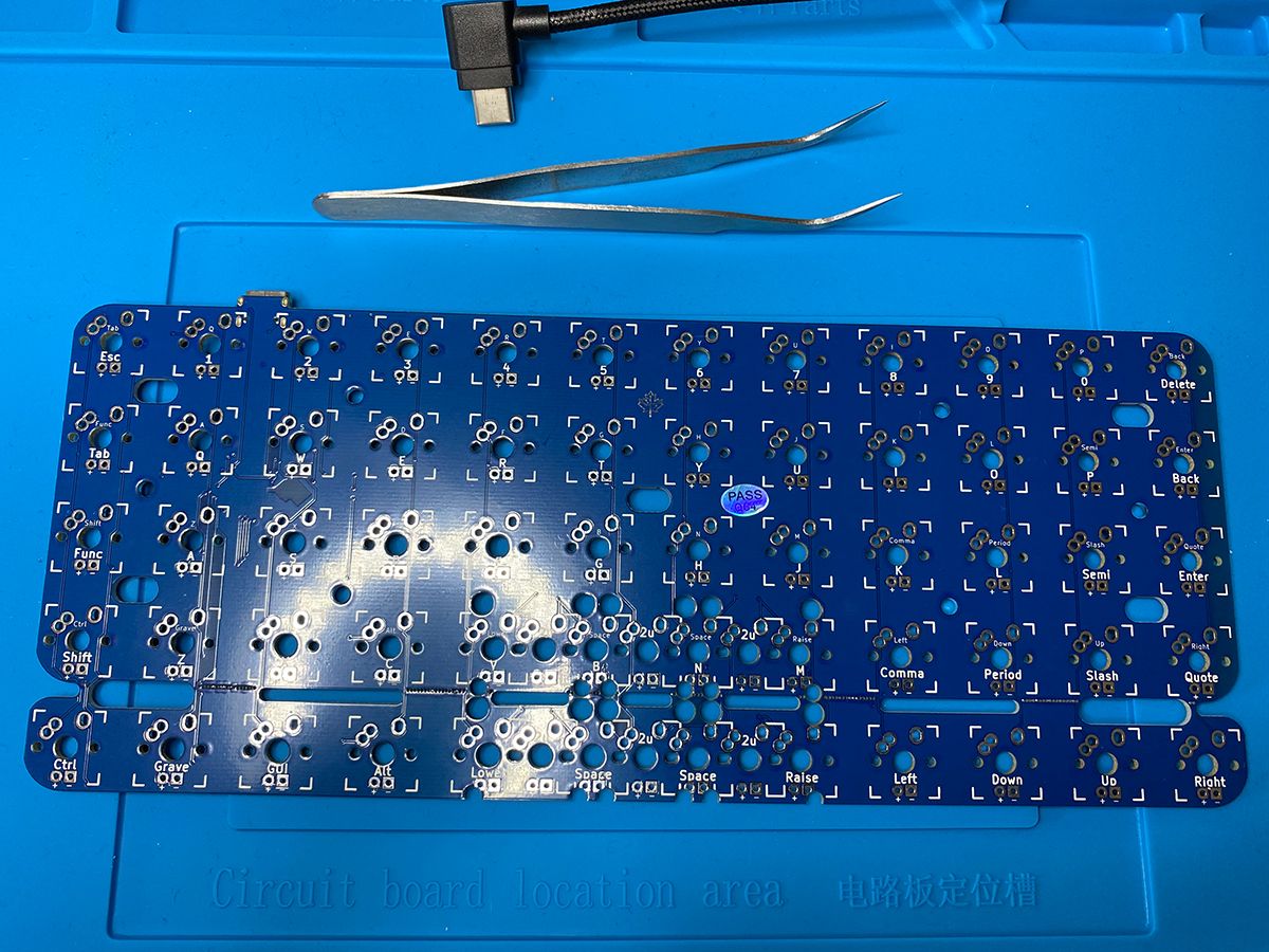
Since the board has two possible layouts, it has two seperate sets of key labels. I used a black permenant marker to cover the labels for the 5x12 layout.
The Curse of the Phantom Firmware
The PCB comes without firmware loaded. No problem, it's QMK compatible and QMK has an online layout creator and easy tools for firmware flashing. Easy peasy. Let's load the 4x12 firmware.... wait... what the hell?
For some reason, the online configurator isn't pulling the default_4x12 layout. Ugh-fine-whatever. I should submit a pull request to fix this. I need to fix it for me first though. Checking out the QMK Firmware documentation, I followed the steps for setting up my build environment. Everything installed as expected.
Let's run qmk setup...
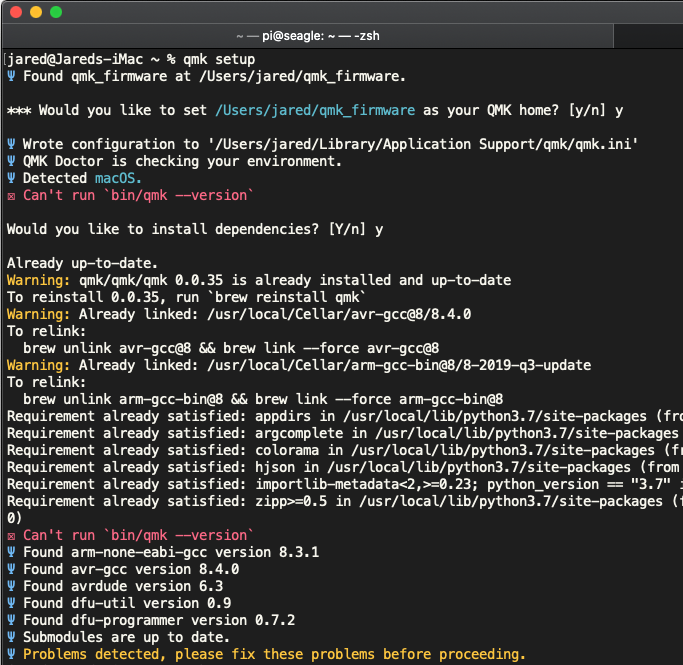
Goddamit. I think this is an issue with where brew links the bin and where the qmk software goes to check it. Whatever - I just need it to work once, gonna ignore this for now.
Using the QMK documentation example, I built this command to compile the firmware I want: qmk compile -kb jnao -km default_4x12
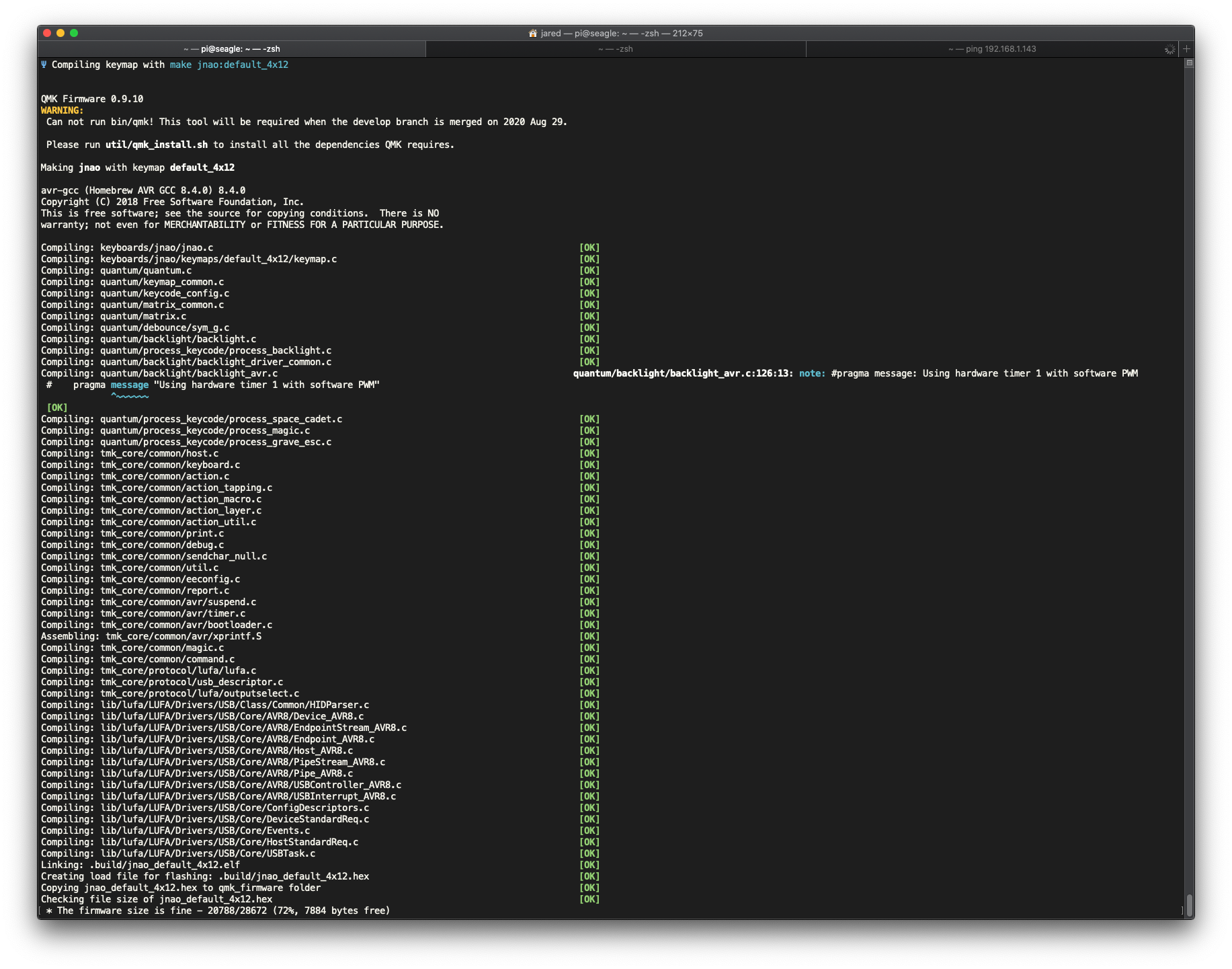
Creating load file for flashing: .build/jnao_default_4x12.hex                                       [OK]
Copying jnao_default_4x12.hex to qmk_firmware folder                                                [OK]
Checking file size of jnao_default_4x12.hex                                                         [OK]
 * The firmware size is fine - 20788/28672 (72%, 7884 bytes free)
This is what I was looking for - a .hex output file to flash to the board.
Using QMK Toolbox, I selected the newly created .hex file and loaded it up. I select JNAO as my keyboard. Hit flash and everthing looks good.
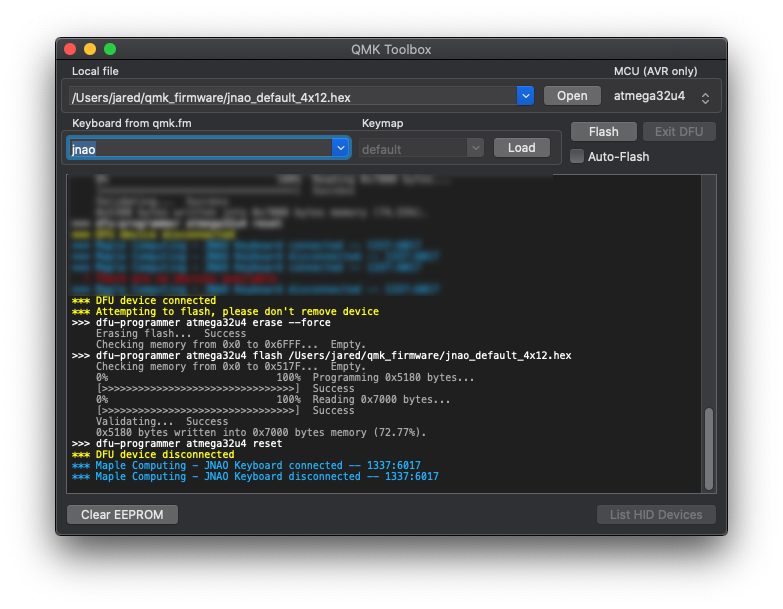
After a typing test, I have the expected default key layout and things seem to be working okay. Just one problem now... I dislike the default layout. Like really dislike it. I want a clone of the Planck layout. I didn't consider that before doing all this work. Back to the drawing board.
I reeeeally don't want to recreate the entire Planck layout by hand for the JNAO board in the QMK Configurator. I have a hunch that I can download the keymap.json file for the Planck, open it up in Sublime Text and change a few lines to create a JNAO keymap.json.
Here we go:
"keyboard":"planck/rev1","keymap":"planck_rev1_layout_ortho_4x12_mine","layout":"LAYOUT_ortho_4x12","I modified that part of the keymap.json with the desired values and saved it as a new file.
"keyboard":"jnao","keymap":"siegel_jnao_layout_ortho_4x12_mine","layout":"LAYOUT_ortho_4x12"After uploading this modified keymap.json to the QMK Configurator site, it loaded all the layers correctly and populated the correct board. Perfect. Compile and then Download Firmware. I used that new .hex file and reflashed the board. Success!✨
You can grab the compiled default firmware and compiled Planck layout firmware off my GitHub: https://github.com/dayofdoom/jnao_default_4x12_firmware
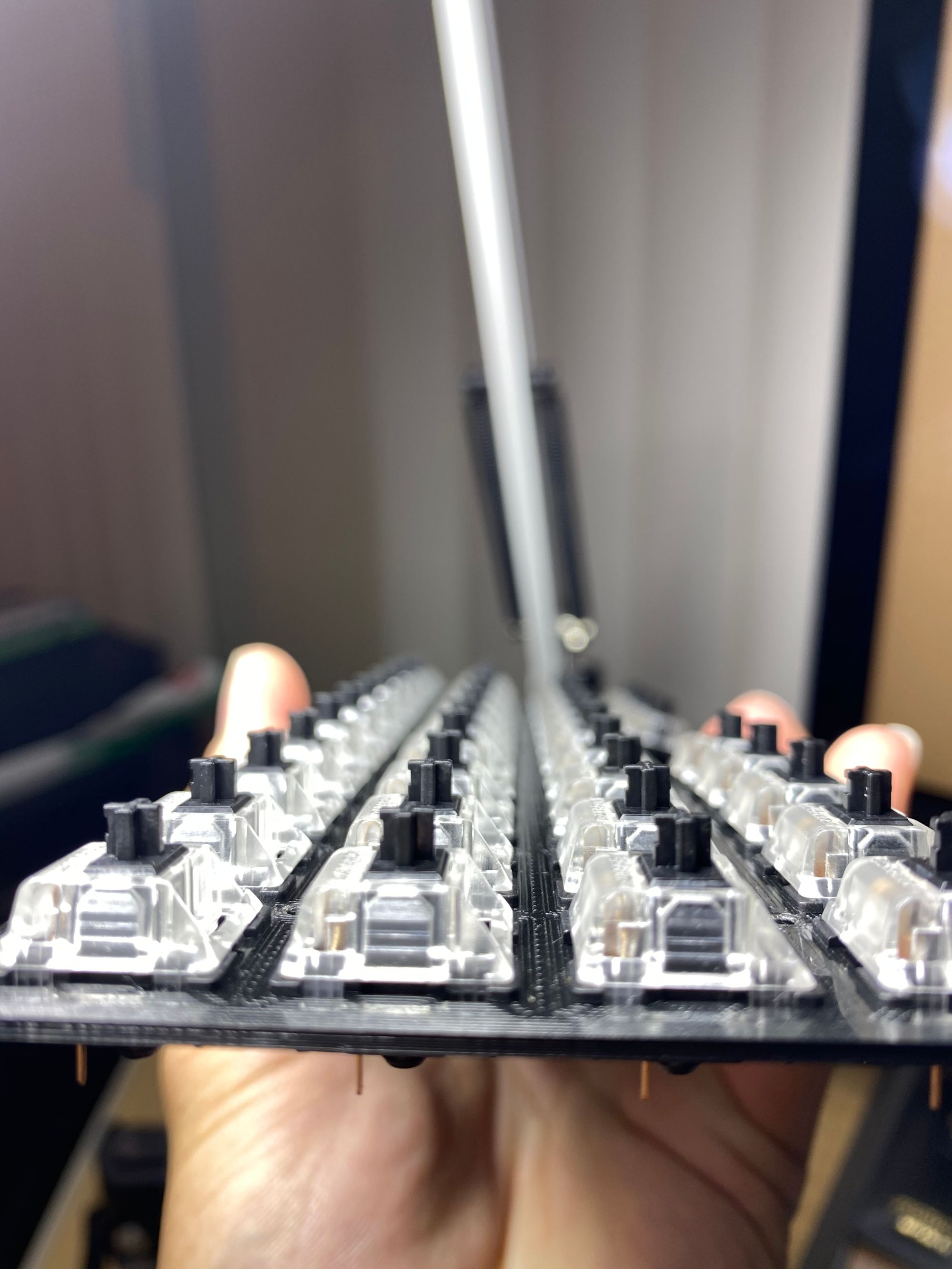
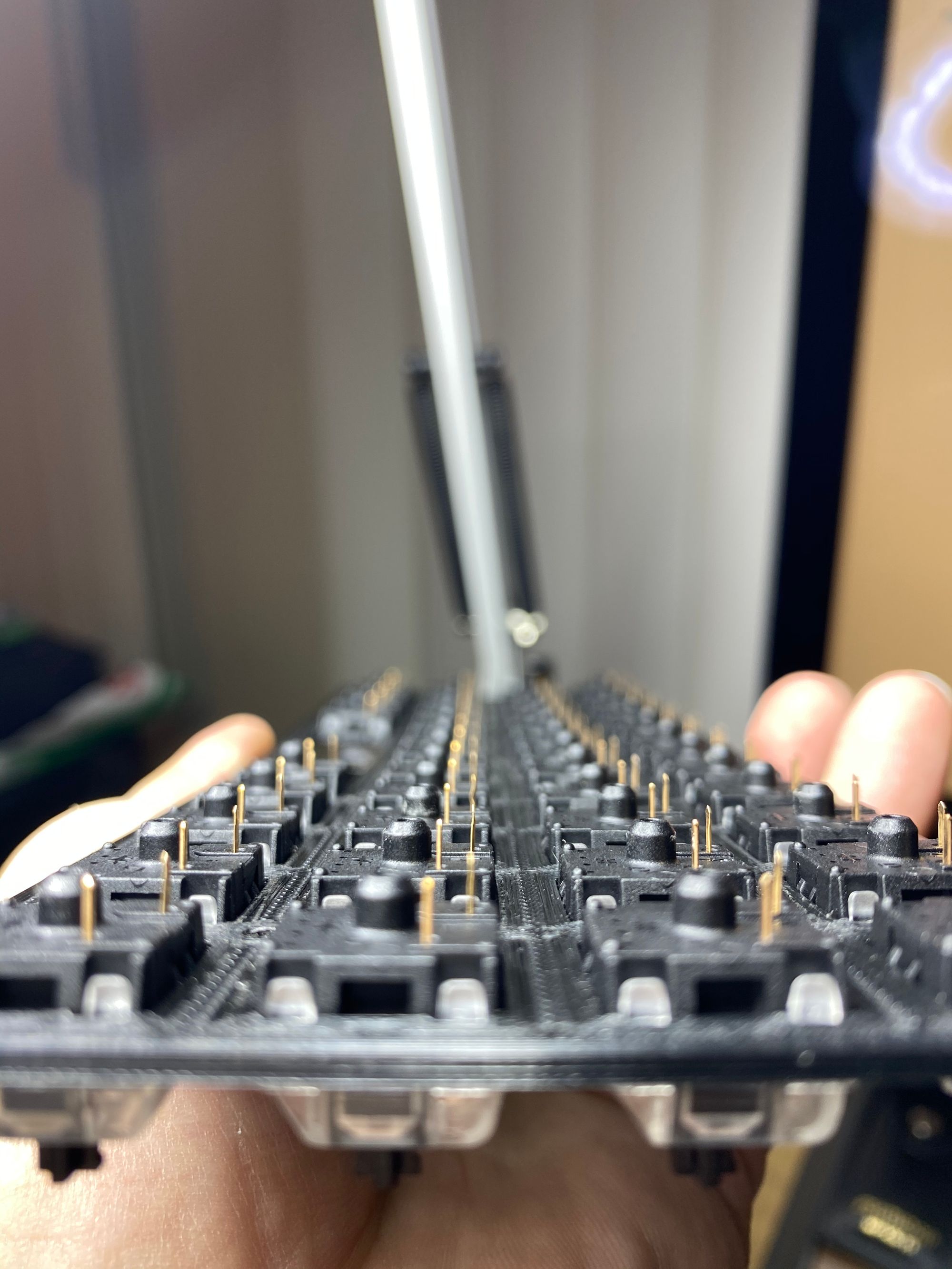
Let's do a sanity test on the newly flashed firmware and make sure the board is doing what it's supposed to do. An easy way to do this is load up the QMK Keyboard Test or the VIA software and then trigger the key using some tweezers.
The key presses registered exactly as they were mapped in the firmware. Perfect.
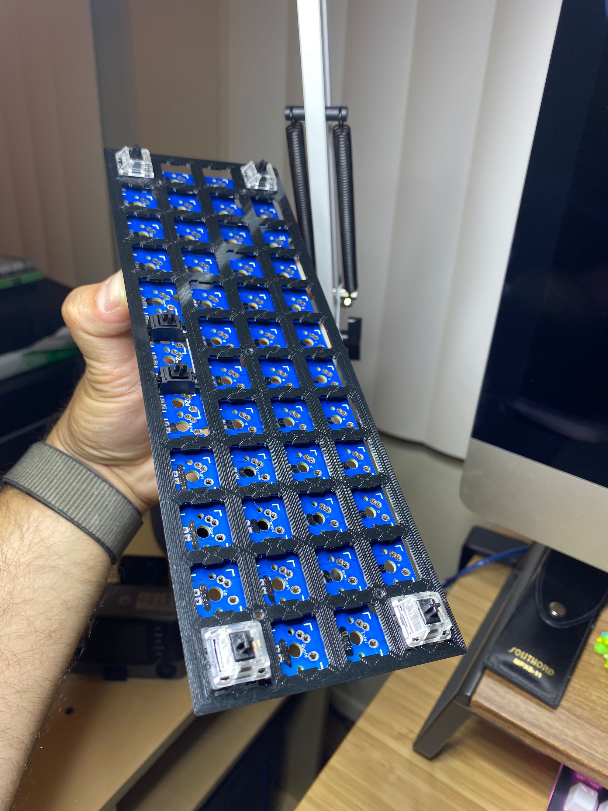
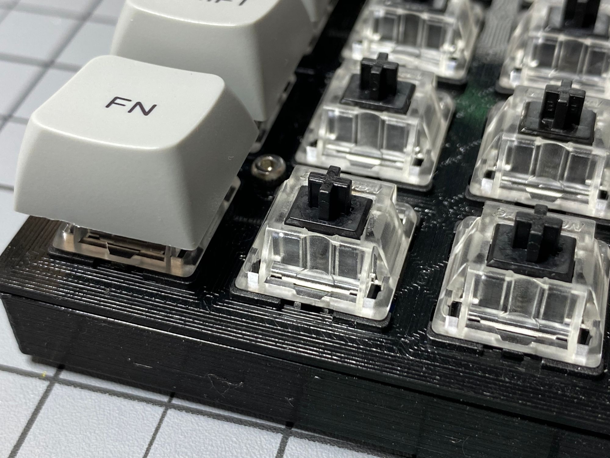
Next I inserted the switches into the top plate and did a test fit with the PCB. The plate and case were 3D printed by my cousin from the lo-pro-bottom.stl and lo-pro-plate-mx-2x2u.stl files in the OLKB GitHub. They came out excellent and give the board a solid foundation with some slight flex. The board is very light too - it feels about the same weight as my cellphone.
Point of no return
In the home stretch here - time to solder the switches to the PCB. I used my Weller WES51 and set the temperature to 600°F. I did each corner of the board first and made sure everthing looked even and level. Then I worked my way through the rest of the switches, pressing down firmly frequently to make sure the switches were completely seated.
After completing the soldering, I opened up VIA and tested all the keys again. I'd rather find a bad solder joint now then after I stick all the keycaps on. Every key was working correctly.🔥🔥🔥.
In Conclusion
The board types nice and smooth. It's audibly pleasing to me. Last touch is to get some rubber feet and stick 'em to the bottom to reduce slide while typing. This was a really fun project. Having this board come together from all the seperate parts was rewarding. 💃