Overview
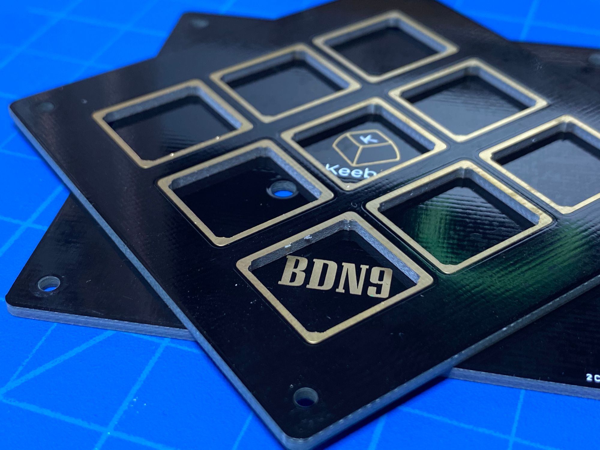
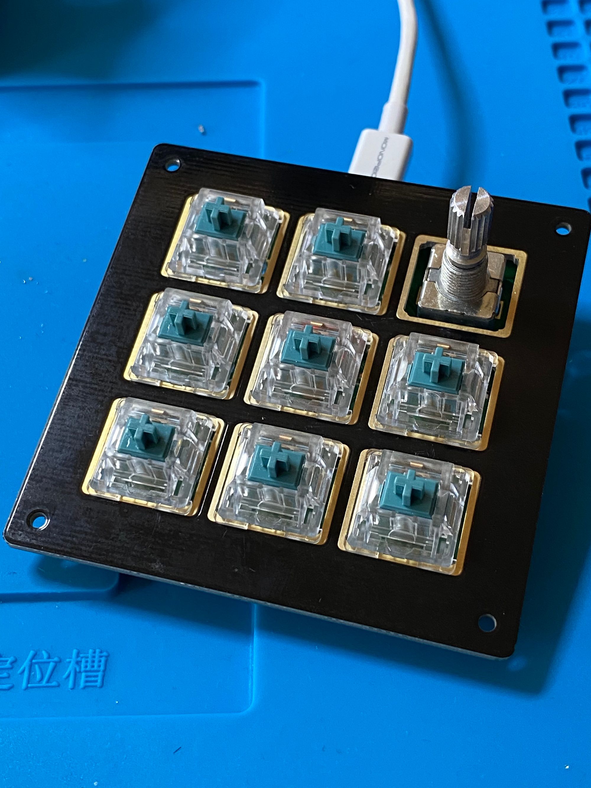
The BDN9 is a macro pad produced by Keebio. It supports four layouts: 3x3 grid, single rotary encoder in the top left or top right, or dual rotary encoders.
I followed the guide at keeb.io.
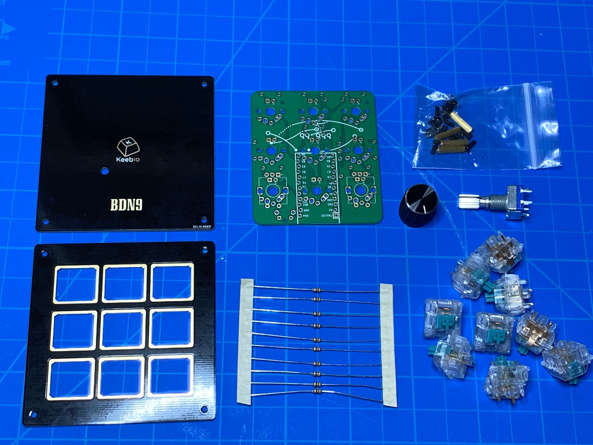
Doing the building part
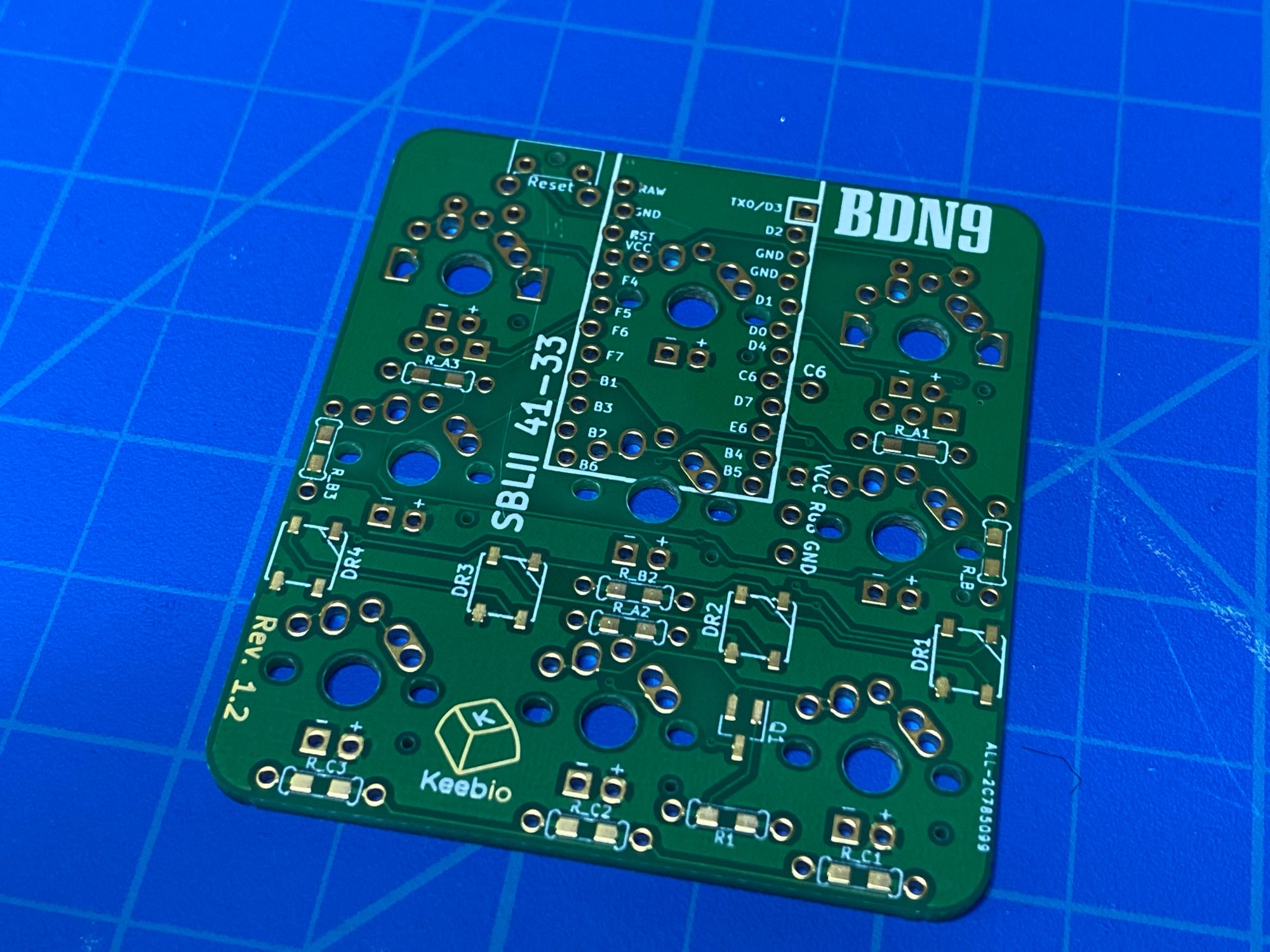
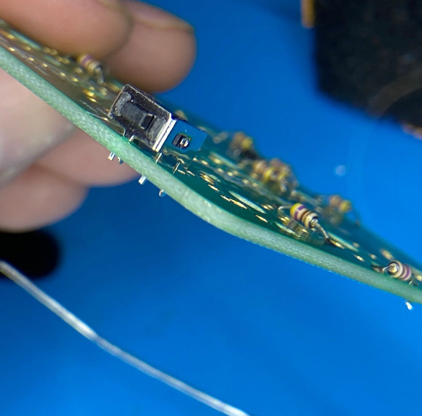
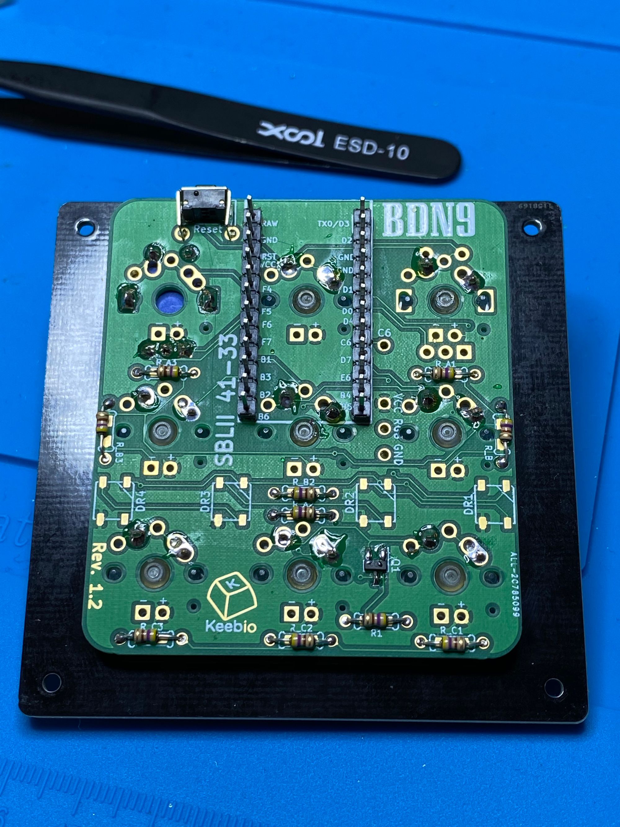
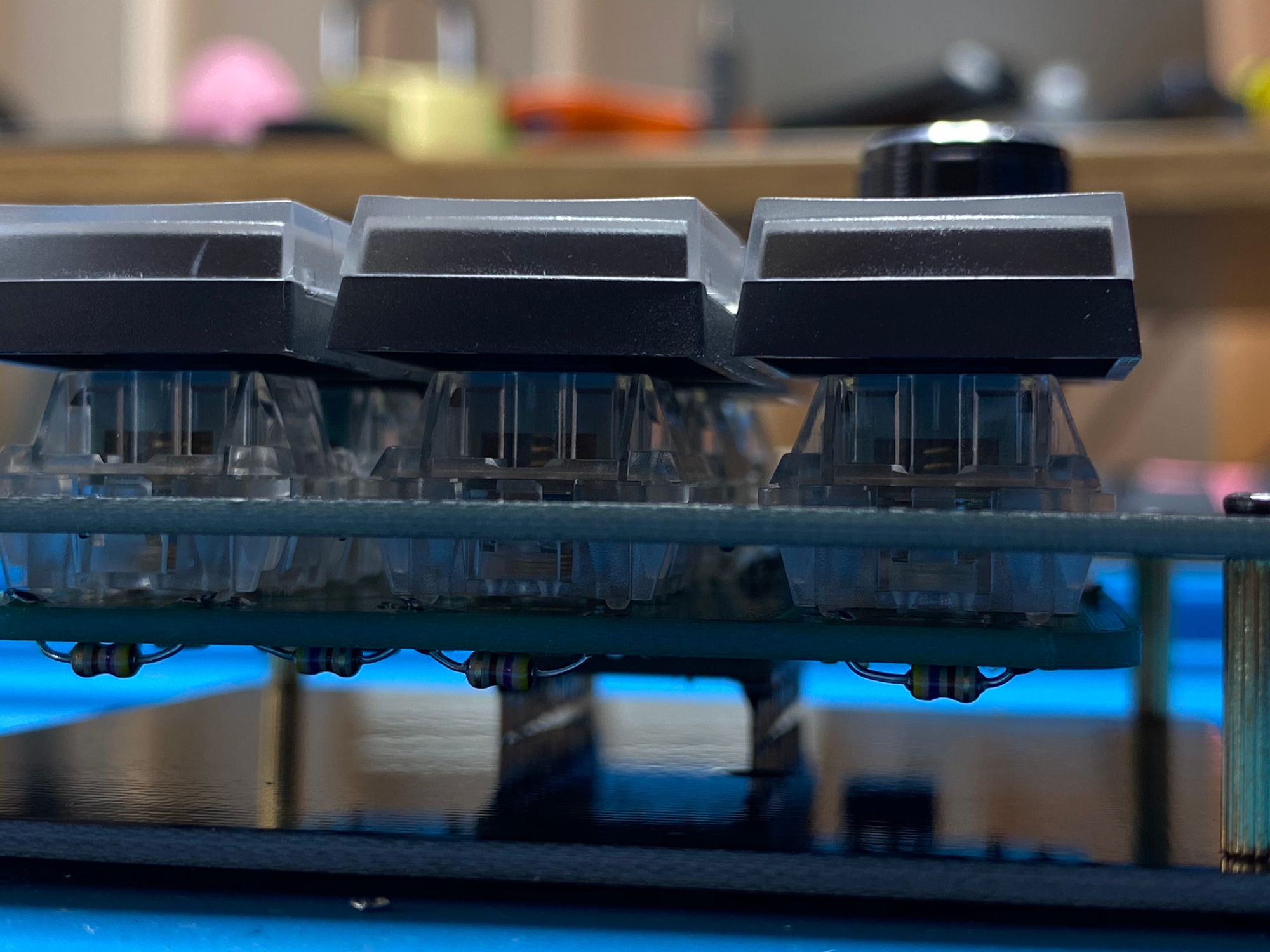
Started by soldering all the resistors.
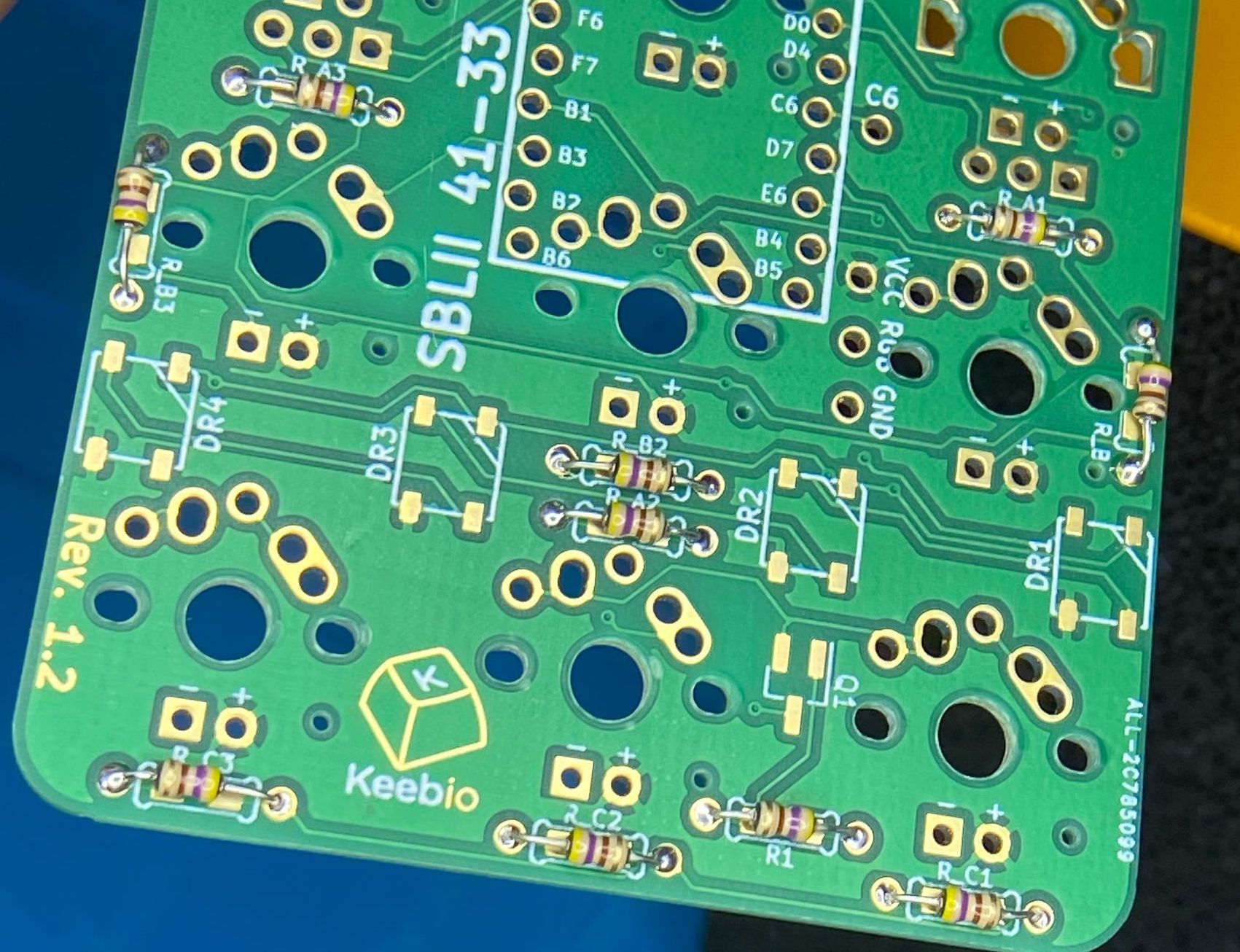
next for the MOSFET and the reset button
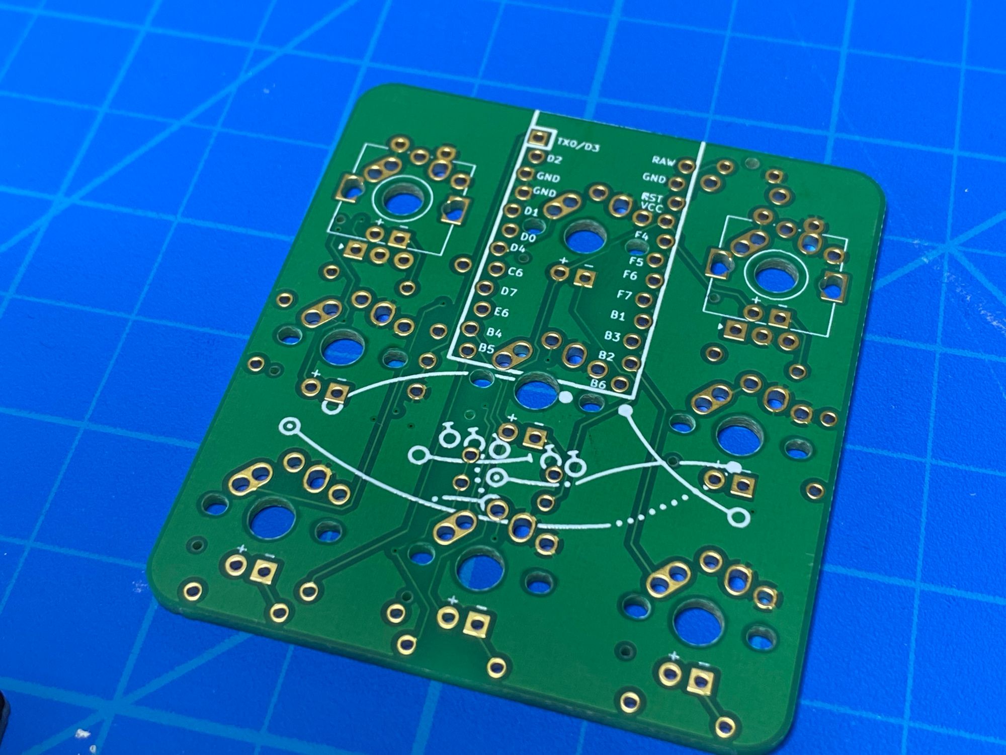
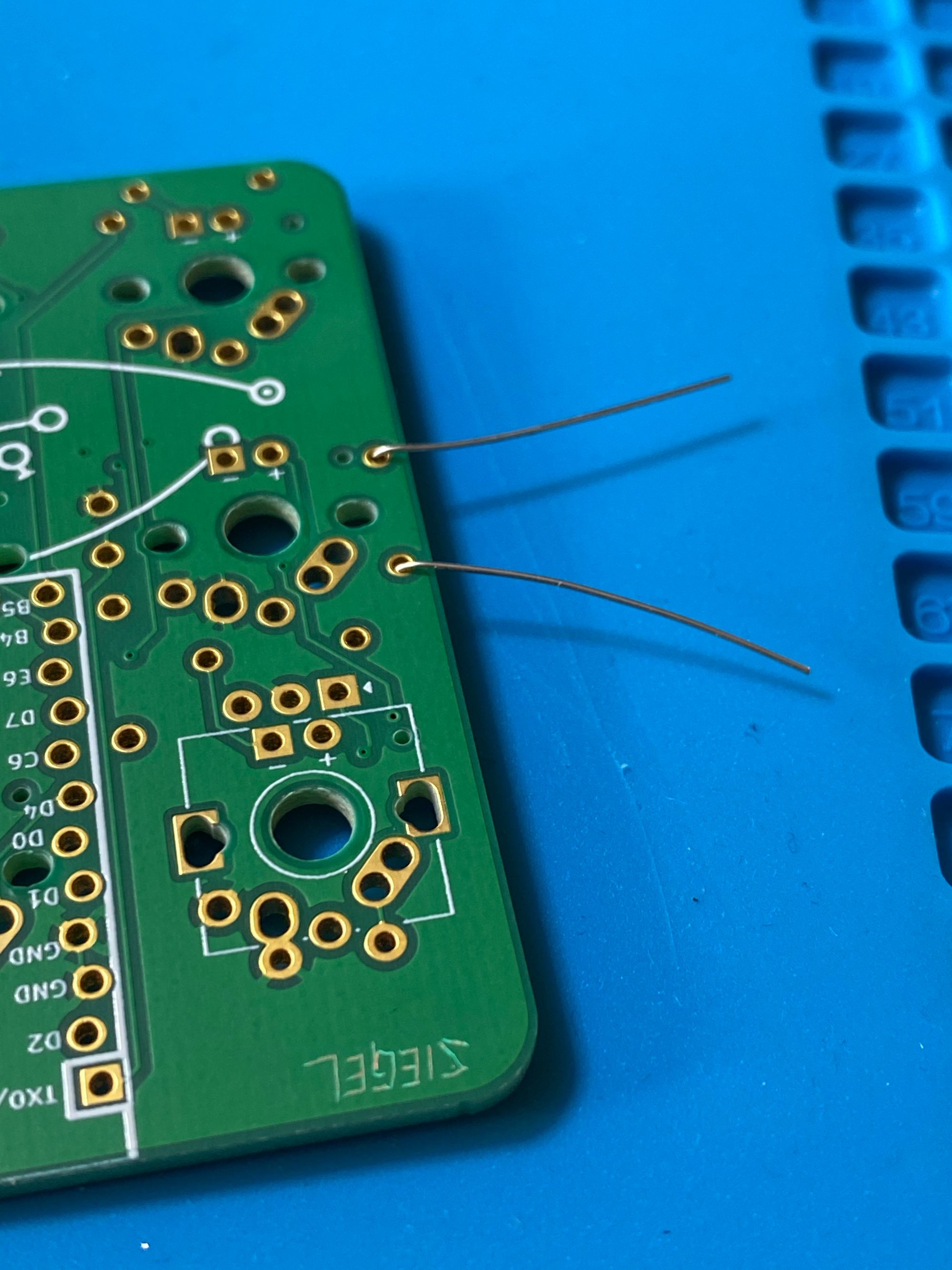
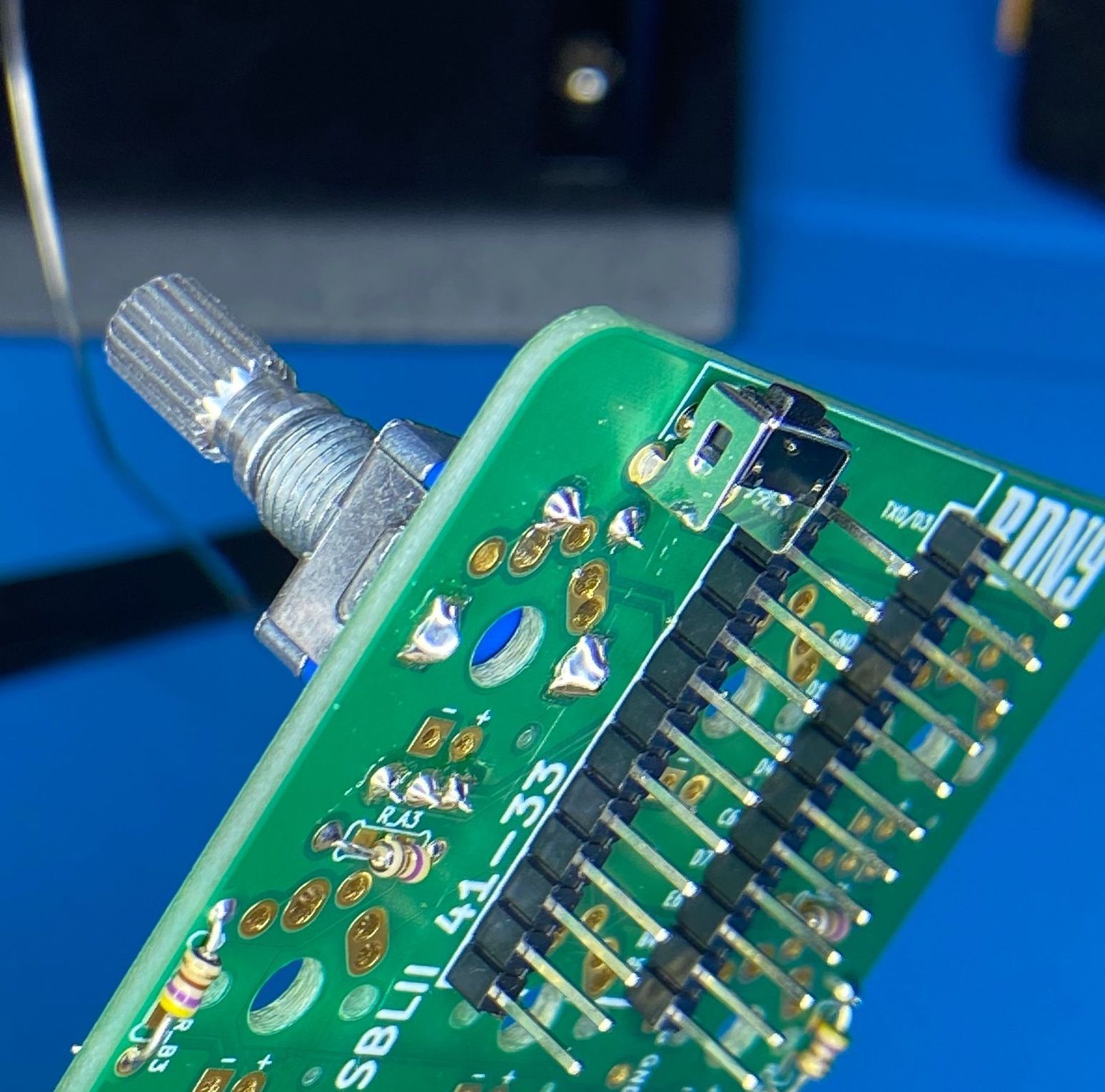
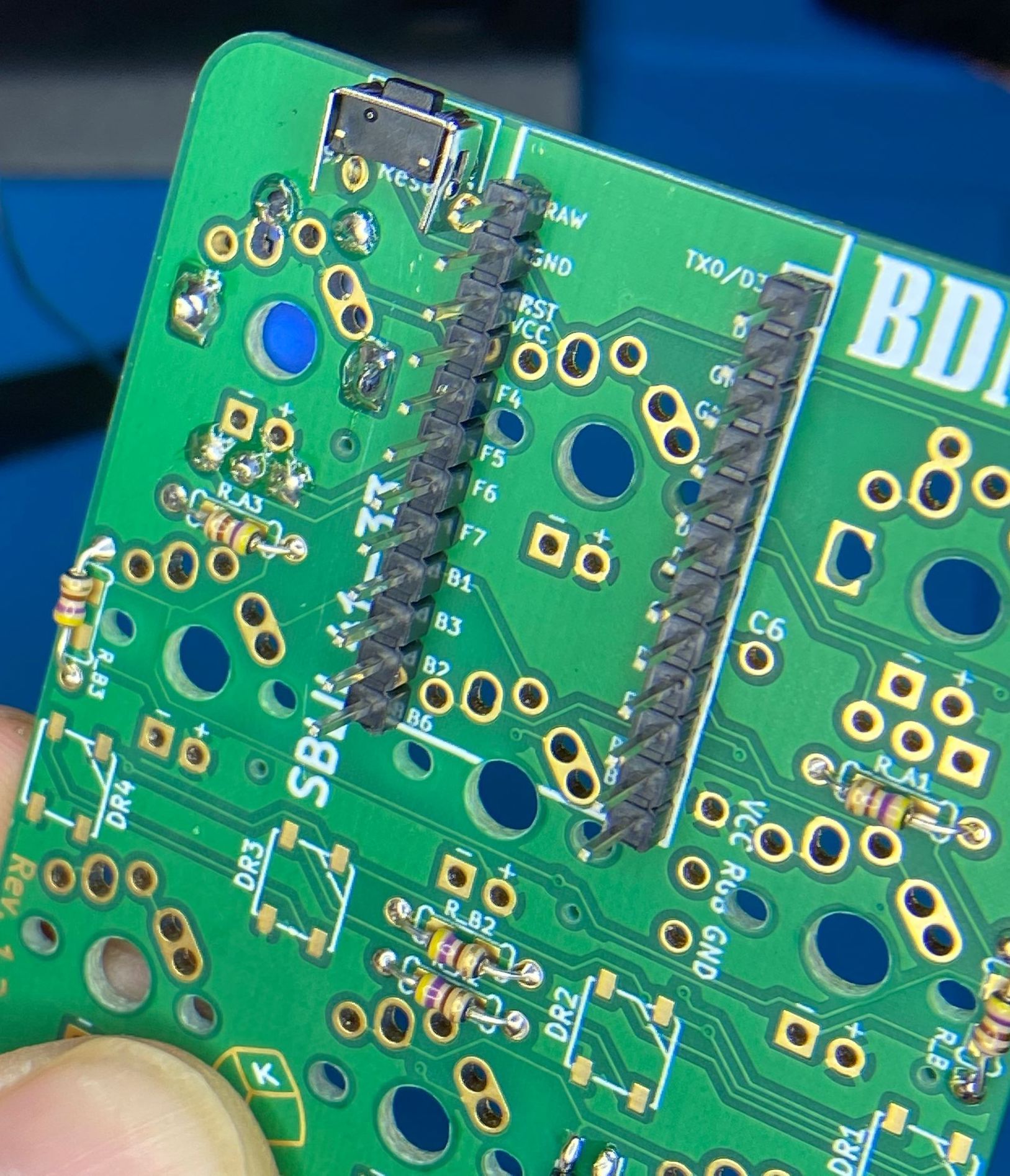
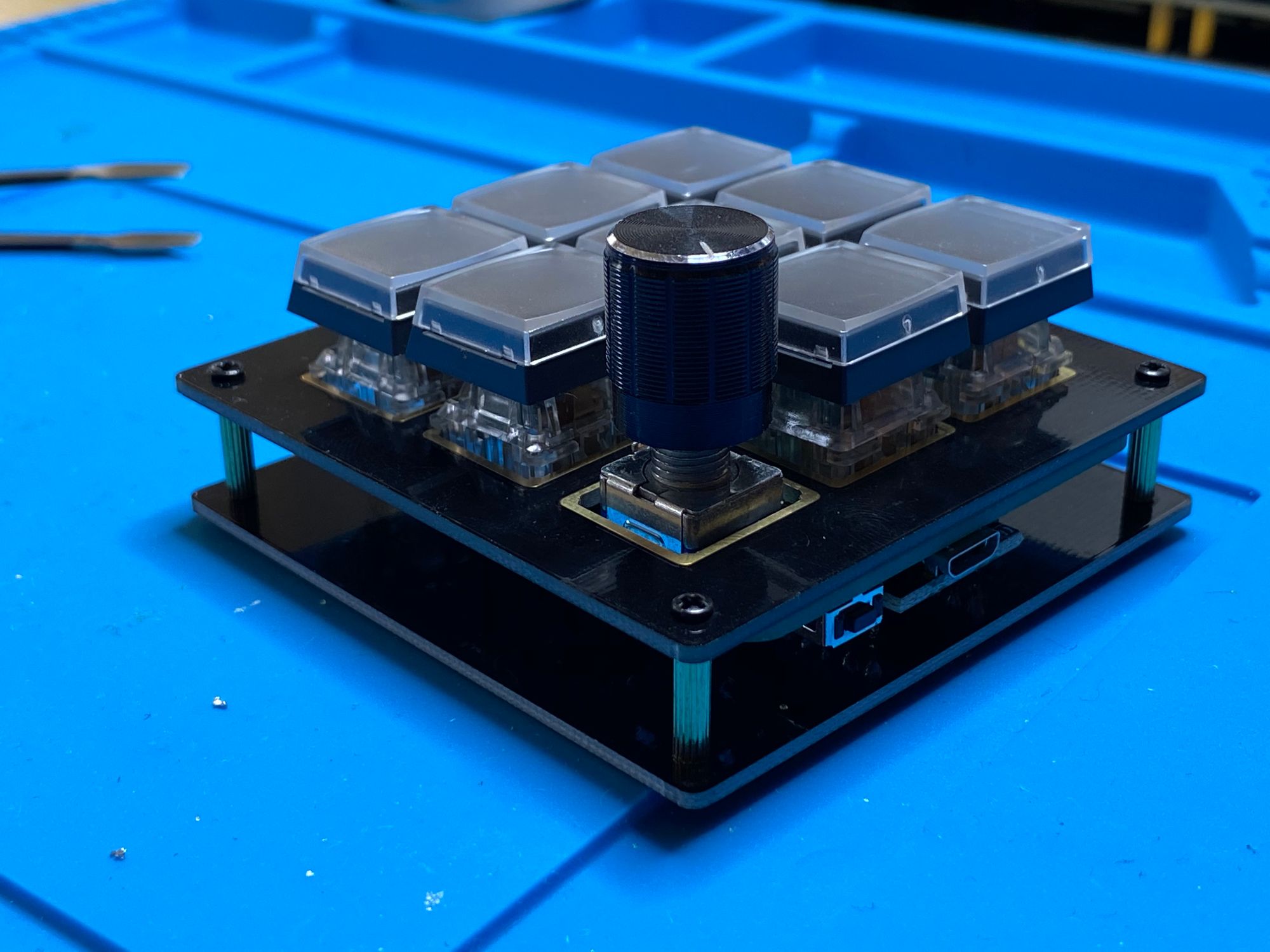
After those, I soldered the pro micro headers into place. The holes are slightly... staggered...? I thought the board was defective but that's just the design. I think it's supposed to allow for the pro micro to be pressure fitted. After the headers were in, I soldered the rotary encoder in place.
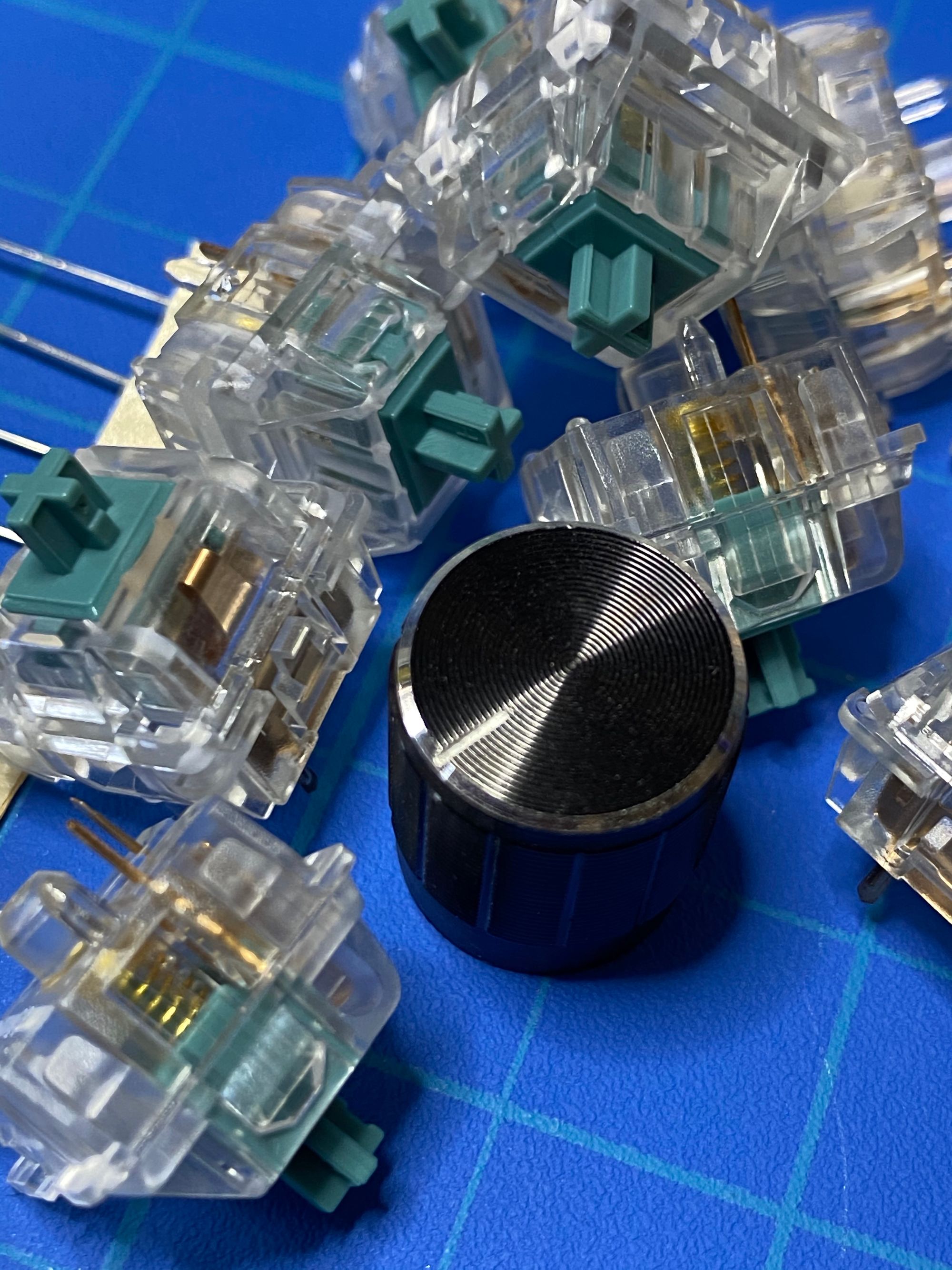
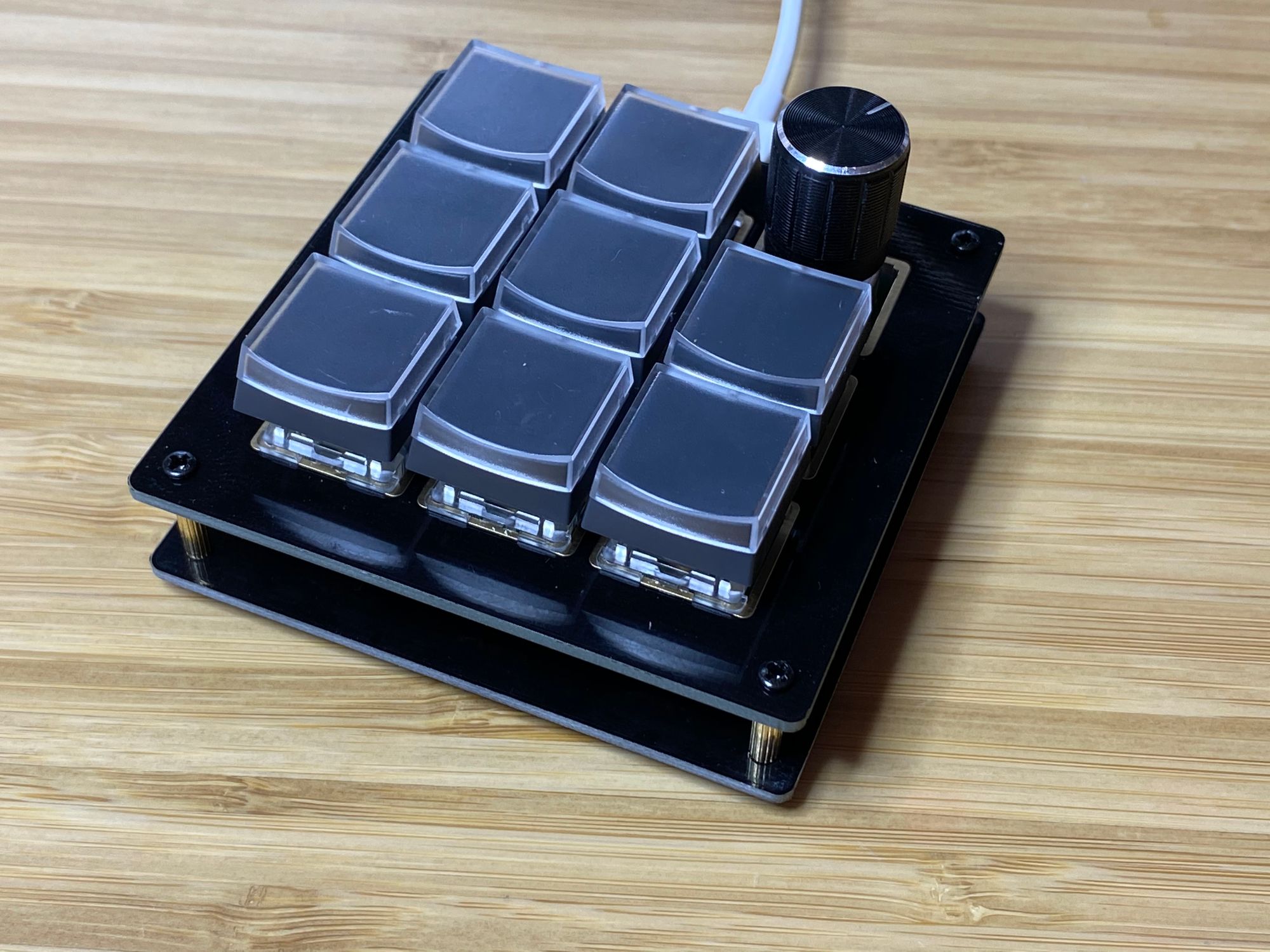
Pressure fitting the switches into the top plate
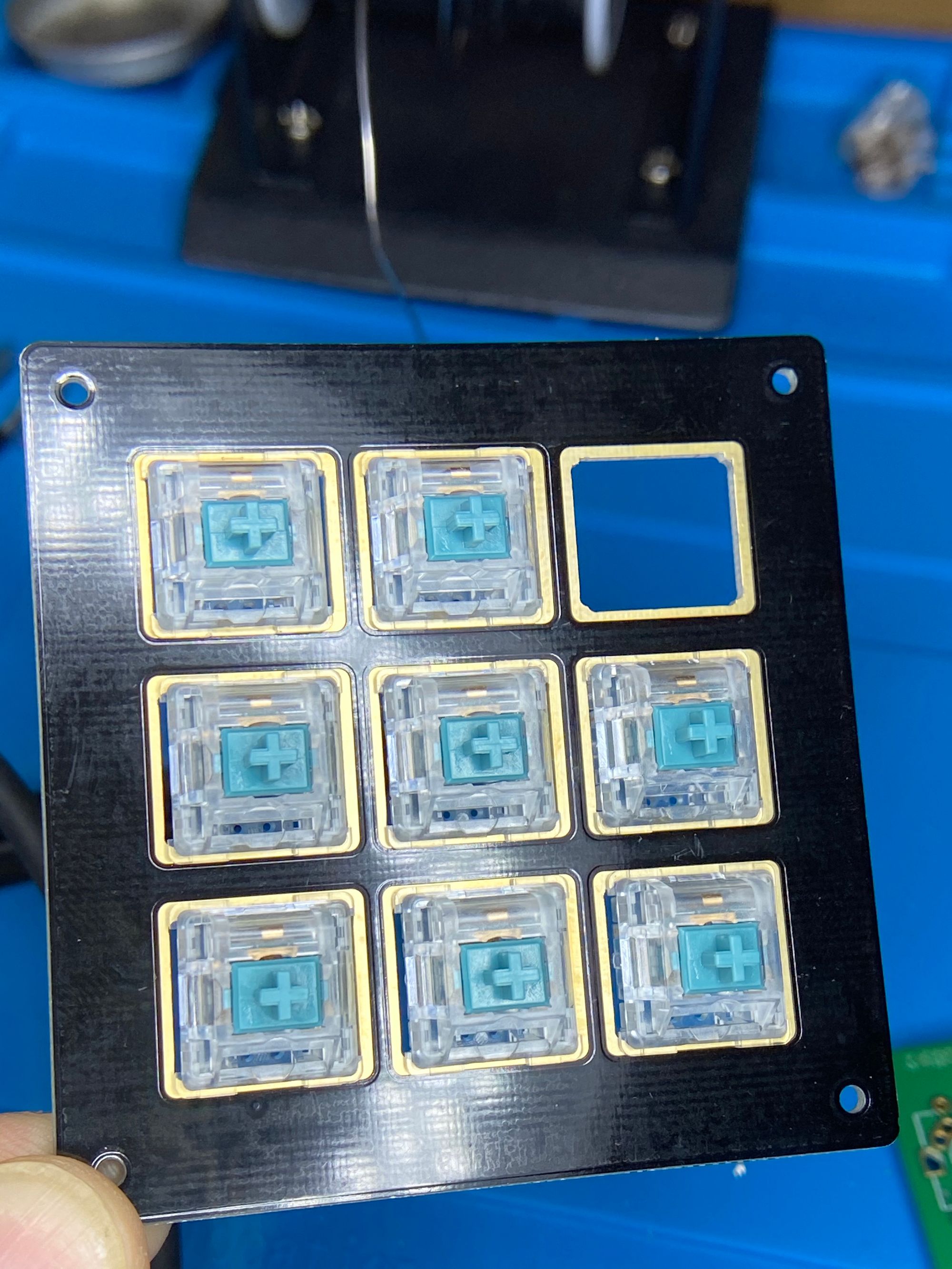
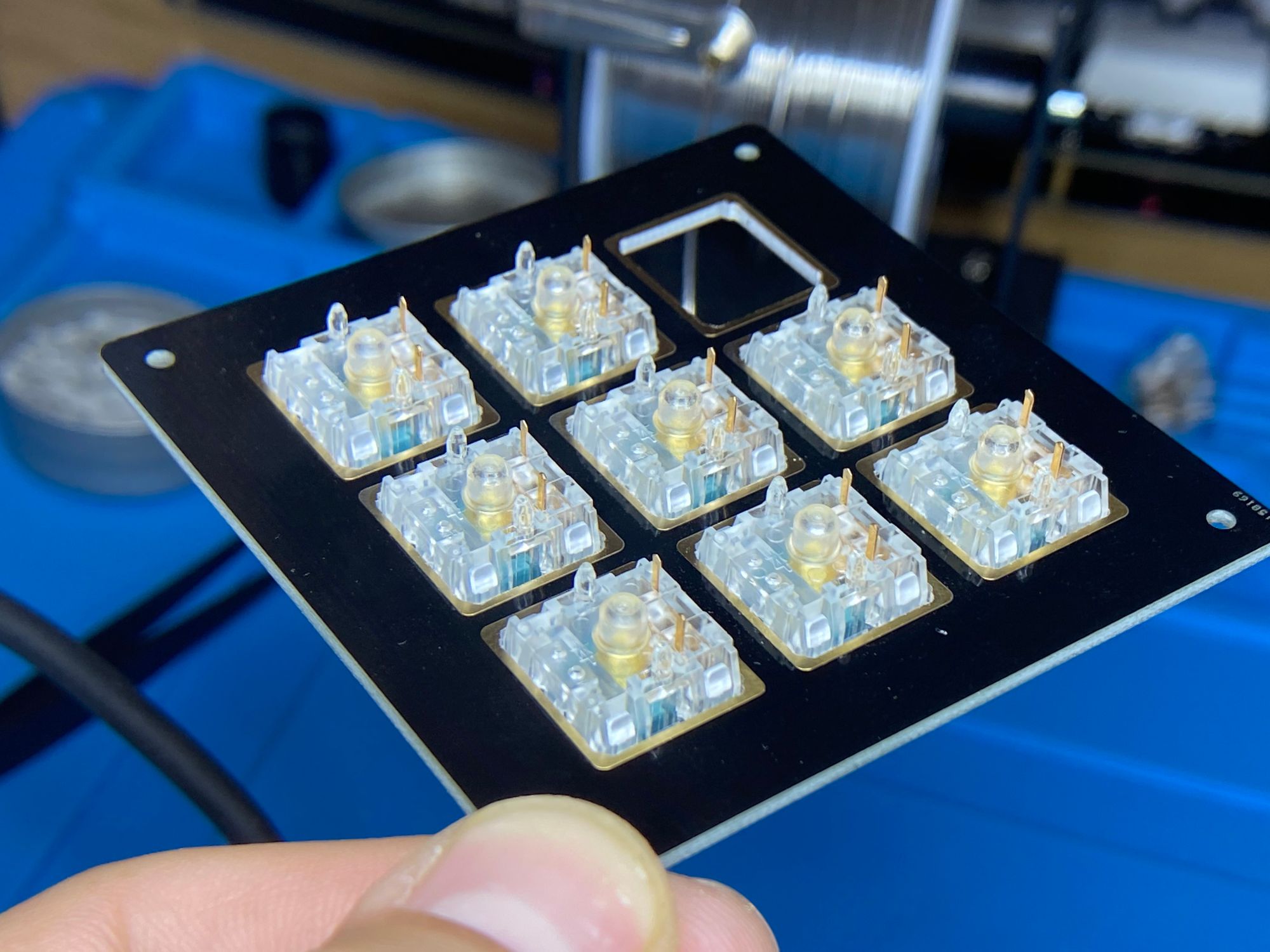
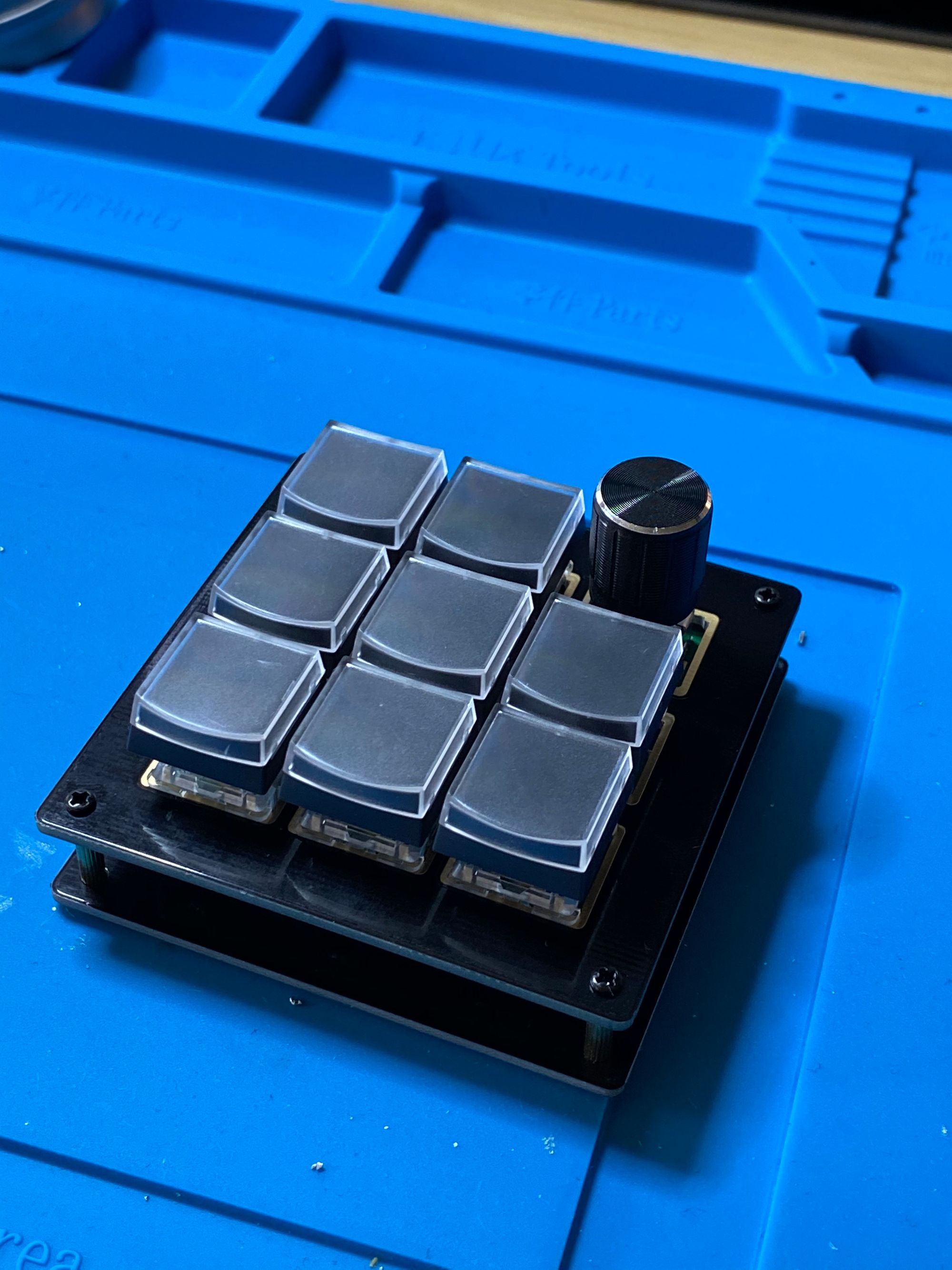
Everything fit well and looked nice. Let's bake this cake.
I was following the keebio instructions and part of them was to place some type of nonconductive barrier between the PCB and the pro micro. While building this I almost didn't do this because it looked liked it would be fine. But I followed the instructions anyways.
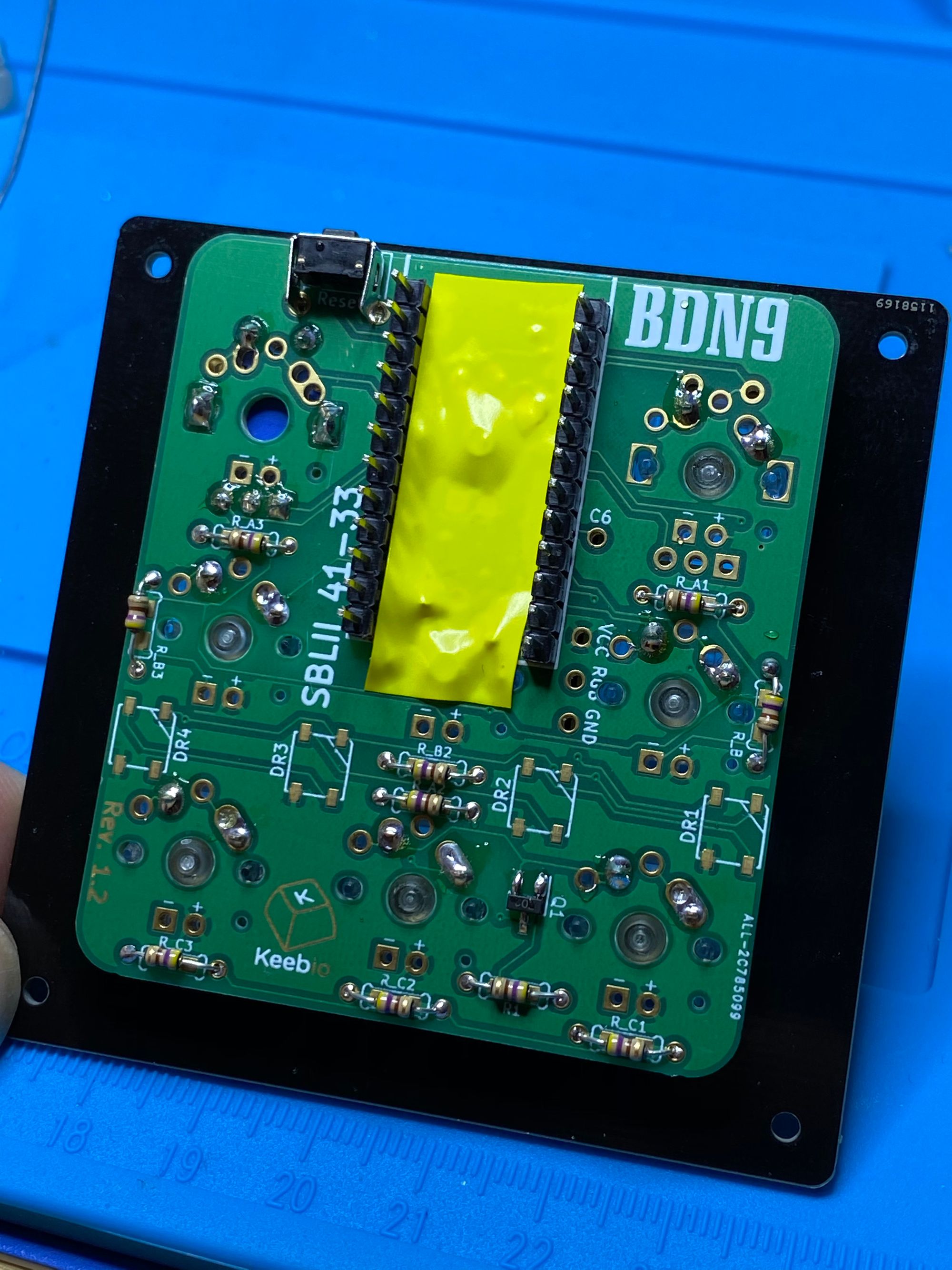
I plopped the pro micro in and melted it. It was a super tight fit. I had to clip the headers with flush cutters to get the base to sit properly. I'm glad I followed the instructions instead of improvising.
Firmware
The main of attractions of this board were the rotary encoders and that there was VIA compatible firmware available. I downloaded the v1 firmware from the VIA website and used QMK Toolbox to flash the pro micro. Did the obligatory clicks and clacks of success and made sure all the switches were passing input.
The stock firmware had a surprisng setting for the right rotary encoder. Twisting left or right triggered the page up/down key codes. Pressing down toggled the mute state. I cloned the QMK firmware repo and found the folder for the VIA firmware for the board. I copied and renamed it. I modified the keymap.c to make twisting the knob raise or lower the volume. Then I complied the firmware with the changes and reflashed the board.
FIN
Side Note
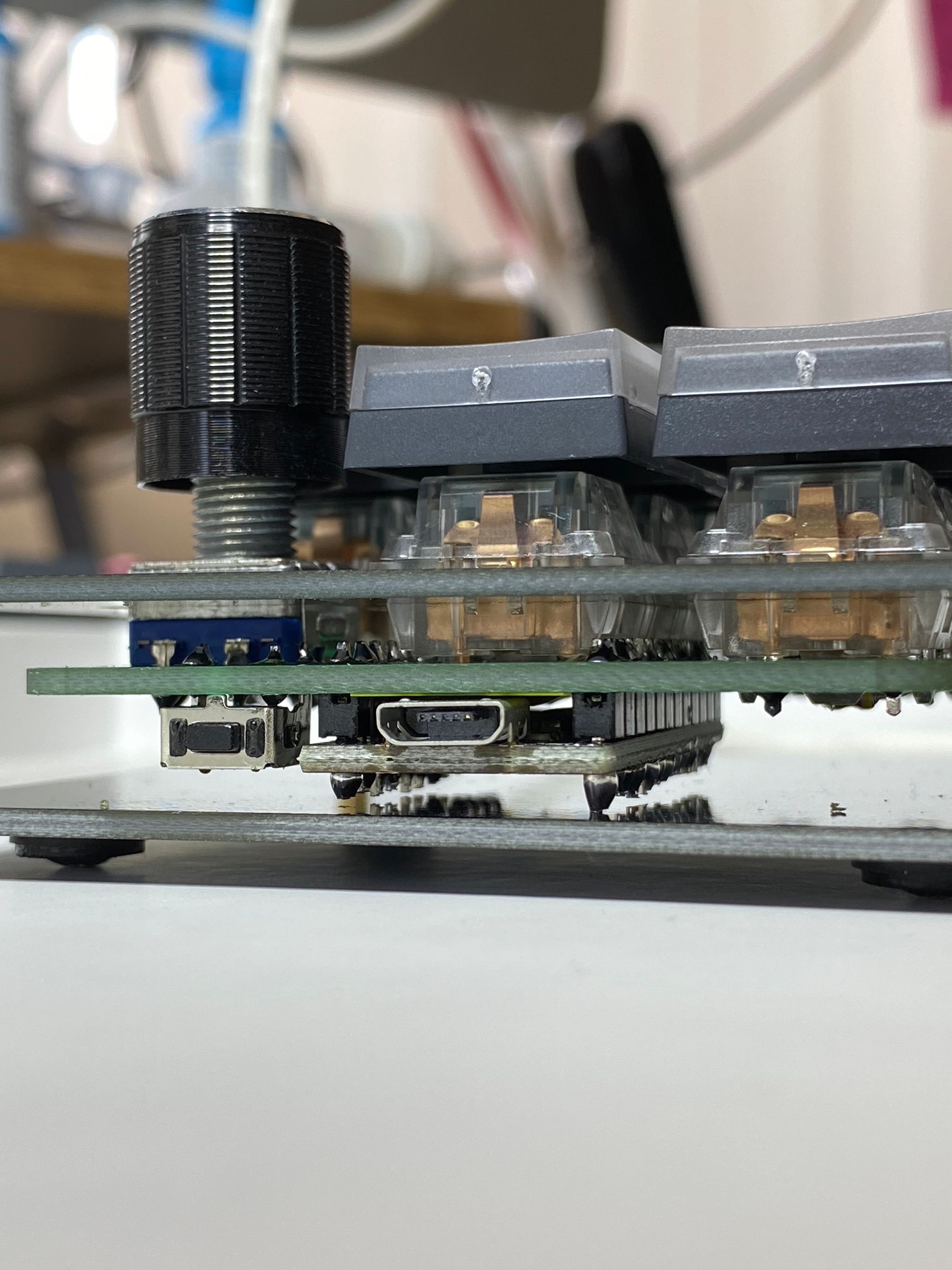
Since the rotary encoder doesn't lock into the switch plate, it dipped a little when I depressed it. I used a hot glue gun and placed a line against the switch plate and the PCB. It's working OK and fixed the issue, but hot glue isn't insulated so... shrug?